23
ENGLISH
13B INSTALLING THE MOTOR LOCK
Install the motor lock, using the supplied screws as shown in Fig. 37
ref. .
Adjust the motor lock as described in chapter 12A of the
assembled automated system installation.
13.1B ADJUSTING THE MOTOR LOCK
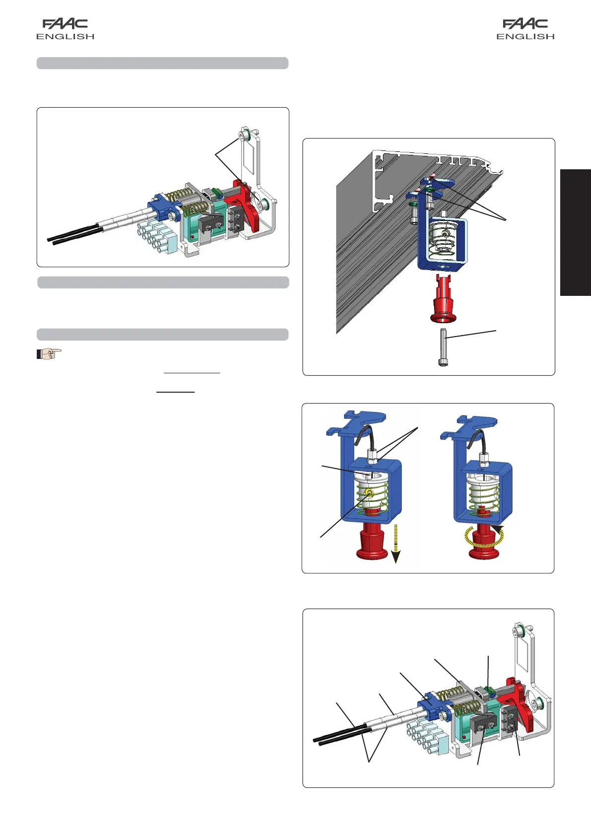
13.2B INSTALLING THE INTERNAL RELEASE KNOB
DOUBLE LEAF APPLICATIONS:
For Vp = (800 ÷ 1000) mm, we advise you to install
the release knob on the side opposite the motor.
For Vp = (1000 ÷ 3000) mm, we advise you to install
the release knob on the same side as the motor.
• Assemble the release knob on the side bracket, as shown in
Fig. 38, after inserting two plates in the profile (Fig.38 ref. )
• Screw the adjuster, with the relevant lock nut, as shown in
Fig. 39 ref. .
• Take about 20 cm of steel cable from the sheath.
• Insert the steel cable inside the adjuster; route it inside the
release device (Fig. 39 ref.).
• Secure the steel cable with the clamp and tighten the screw
(fig. 39 ref.).
• Take the black sheath of the cable in contact with the adjuster
(fig. 39 ref.).
• Fully screw the adjuster on the bracket.
• Lock the knob by pulling and rotating it through 90° making
sure it does not return to its original position (fig. 39).
• Route the cable with sheath inside the cable raceways, until
you reach the motor lock device, avoiding excessively tight
sheath curves.
• Take the cable with sheath to detail in figure 40, and cut
excess sheath.
• Route the cable (fig.40 ref.) inside detail , taking the
sheath to its contact point (fig. 40 ref. ).
• Insert the cable in the clamp (Fig.40 ref.).
• Pull detail to its contact point (compressing the springs)
and fasten the screw of the clamp , thus securing the
steel cable.
• Cut the excess portion of the steel cable.
• Make sure that the motor locking device coupling is free of
the motor shaft coupling (fig.27 ref A).
• If any adjustments are necessary, use the adjuster of the knob
bracket (Fig. 39 ref. ).
• Release the knob, turning it through 90°, and check if the
release functions. Also check if the door opening microswitch
(fig.40 ref.) is activated by pulling the knob.
For electrical connection of the motor locking device, consult
the section on the control board in these instructions.
If it is necessary to install the external release device, use the
key-operated push-buttons. Fit the release cable on the motor
locking device, using the appropriate seat (fig. 40 ref. ).
fig. 37
fig. 39
fig. 40
fig. 38