3
115V/230V~
RX
TX
ENGLISH
MODEL A100 COMPACT A100 COMPACT 2
No. of leaves 1 2
Max leaf weight 110 Kg 70 + 70 Kg
Transit space (VP) 700 ÷ 3000 mm 800 ÷ 3000 mm
Max thickness of framed leaf 60 mm
Use frequency 100 %
Protection class IP 23 (for indoor use)
Operating ambient temperature -20°C ÷ +55°C
Power supply 115V/230 V~ 50/60 Hz
Max absorbed power 100 W
Beam length Vp x 2 +100 mm
Drive unit 24 Vdc with encoder
Opening speed adjustment (load free) 5 ÷ 70 cm/sec. 10 ÷ 140 cm/sec.
Closing speed adjustment (load free) 5 ÷ 70 cm/sec. 10 ÷ 140 cm/sec.
Partial opening adjustment 10% ÷ 90% of total opening
Pause time adjustment 0 ÷ 30 sec.
Night pause time adjustment 0 ÷ 240 sec.
Static force adjustment automatic
Anti-crushing device active at opening/closing
Failsafe on photocells Yes (can be activated by programming)
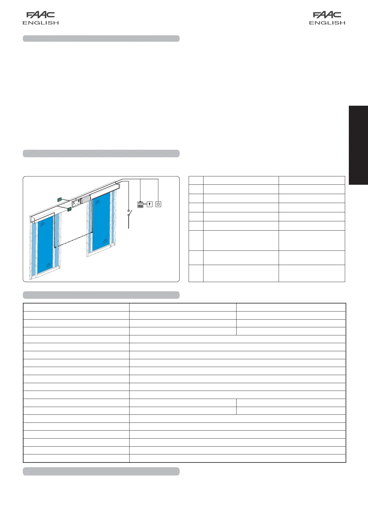
2 ELECTRICAL PREPARATIONS
3 TECHNICAL SPECIFICATIONS
Route the electrical cables for connecting the accessories and
electrical power supply as shown in Fig. 2.
N° DESCRIPTION CABLES
External radar 4x0.25mm²
Internal radar 4x0.25mm²
Photocell transmitter 2x0.25mm²
Photocell receiver 3x0.25mm²
SD-Keeper / SDK-Light 2x0.5mm² max 50 m
Key operated switch
for locking SD-Keeper /
SDK-Light (future accessory)
2x0.5mm²
Control push-buttons
Emerg/Key/Reset
2x0.5mm²
Power supply
115/230V
~
2x1.5mm² + earth
1.2 DOOR FRAME ACCESSORIES
To facilitate the door profile to adapt to the carriages and to enable correct finish of the installation, FAAC offers the following
series of articles:
Pair of sliding blocks (fig. 12-13 ref. )
Supplied as a pair, they can be secured on a wall (or on the fixed leaf) or directly on the floor.
Lower guide profile (fig. 12-13 ref. )
For adapting the lower profile of the leaf to the above sliding blocks.
Brush for lower guide profile (fig. 12-13 ref. )
Completes the on-floor guide system.
Leaf fitting profile (fig. 10 ref. )
Adapts the leaf’s top profile to the carriage fittings.
Pair of lower sliding blocks for glass panel leaf
They enable the glass leaves to slide
4 CROSS BEAM CONFIGURATION
To suitably position the cross beam components, refer to the
dimensions in figures 5, 6, and 7.
fig. 2