BEISSBARTH MT 870 / MT 880
4-2
Middle-centring flange
For all wheels with a middle hole for centring (about 80% of all wheels), the middle-centring flange
is used to clamp the wheel to the balancing machine.
To keep clamping errors as low as possible, always position the wheel with the tyre valve at the bot-
tom when clamping the wheel to the flange or fitting it to the vehicle.
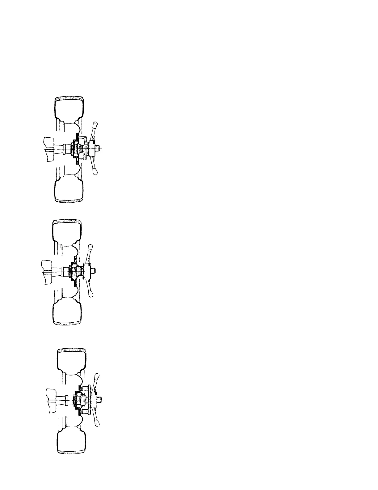
1. Centring of the wheel with centring cones from the back of the rim,
and securing with clamping cover and toggle nut from the front:
Push the coil spring over the flange shaft. Select the matching centring
cone (the cone must enter the middle-centring hole on the wheel) and
push it against the coil spring. Hold the wheel carefully against the
centring cone and at the same time press the clamping cover over the
flange shaft and against the wheel. Secure the wheel by hand, using the
toggle nut. Never use any tools, for instance a hammer.
(See Fig. 1.)
2. Centring of the wheel with centring cones from the back of the rim,
and securing with pressure ring and toggle nut from the front:
Centre the wheel as described in Item 1 above. The wheel is secured by
a pressure ring instead of the clamping cover. This applies to alloy
wheels with a very high dome formed in the wheel, so that the clamping
cover does not make good contact, or the wheel pattern is irregular
(reinforcing ribs).
(See Fig. 2.)
3. Centring of the wheel with centring cones from the back of the rim,
and securing with centring washers and toggle nut from the front:
The wheel is centred from the back, as described in Item 1 above. It is
secured by a centring disc (types available to suit specific cars) instead
of the clamping cover. The centring disc has fixed pins which locate in
the corresponding wheel attachment holes and press the wheel against
the flange contact face when the toggle nut is tightened.
(See Fig. 3.)
Fig. 1
Fig. 2
Fig. 3