Operation - RT10
31
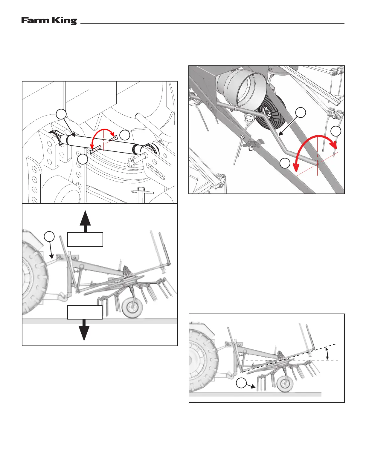
Tilt Adjustment
Three-Point Hitch
Figure 25
Turn in/out the top linkage (Item 1) of the three-
point hitch to change the rotary unit tilt with respect
to the ground [Figure 25].
Turn the linkage counter clockwise (Direction A)
to extend the rod and push the equipment frame
upwards, reducing the inclination [Figure 25].
Turn the linkage clockwise (Direction B) to retract
the rod and pull the equipment frame downwards,
increasing the inclination [Figure 25].
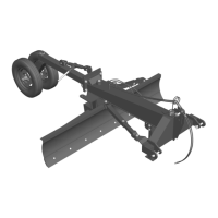
Pull-Type Hitch
Figure 26
Turn the adjustment lever (Item 1) of the pull-type
hitch to change the rotary unit tilt with respect to
the ground [Figure 26].
Turn the lever counter clockwise (Direction A) to
push the equipment frame upwards, reducing the
inclination [Figure 26].
Turn the lever clockwise (Direction B) to pull the
equipment frame downwards, increasing the
inclination [Figure 26].
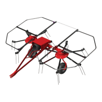
Operating Angle
Figure 27
For best results, operate the tedder at an angle of
7—10°. The front tines (Item 1) should graze the
ground [Figure 27].
1
1
B
B
A
A
1
TILT FRAME
UP
TILT FRAME
DOWN
7—10°
1