AM-JACKAL-35/ JULY 2020
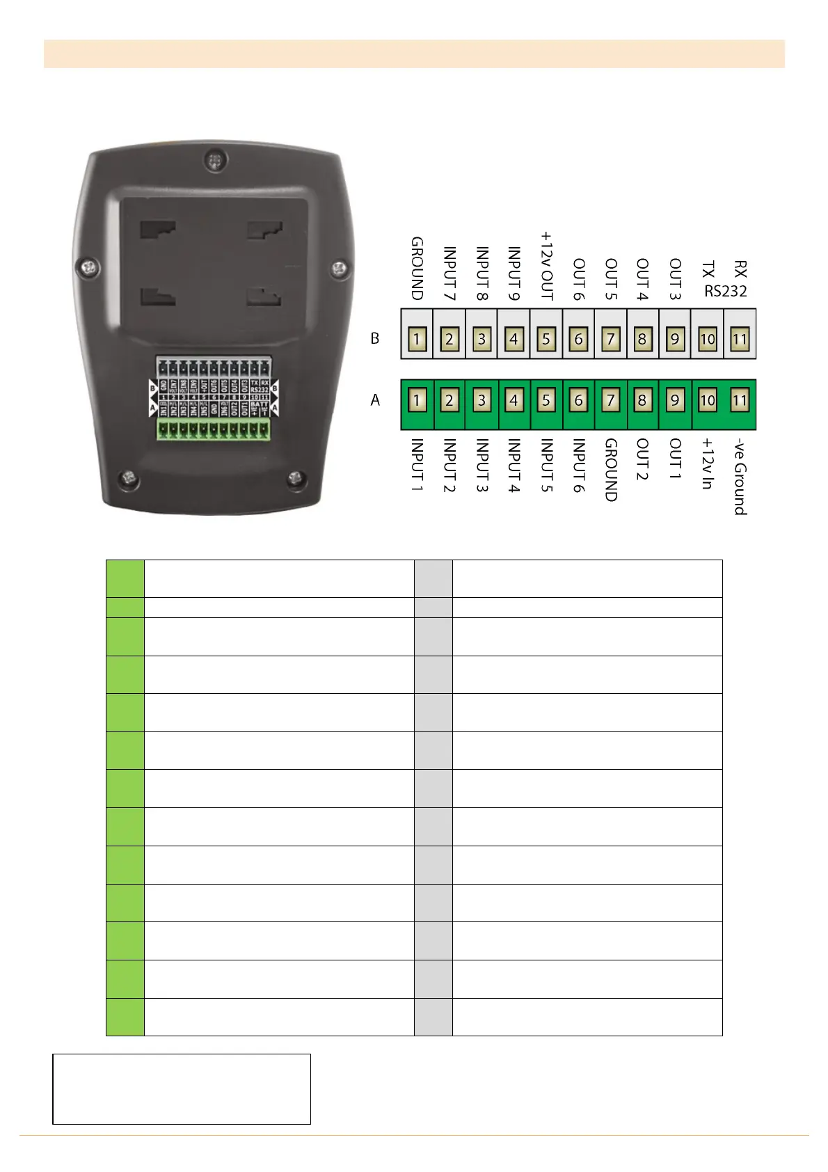
REAR CONNECTIONS (MONITOR & CONTROL VERSION)
The connector on the rear of the Jackal Monitor & Controller has the following points available for use when the
supplied Tractor & Section/Implement harness is not used.
INPUT 1
Prox / Reed / High-Low / On-Off / Alarm
INPUT 2
Prox / Reed / High-Low / On-Off / Alarm
INPUT 7
Varying Voltage Sensor
INPUT 3
Prox / Reed / High-Low / On-Off / Alarm
INPUT 8
Prox / Reed / High-Low / On-Off / Alarm
INPUT 4
Prox / Reed / High-Low / On-Off / Alarm
INPUT 9
Prox / Reed / High-Low / On-Off / Alarm
INPUT 5
Prox / Reed / High-Low / On-Off / Alarm
+12v OUT
Supply Out / Sensor Power
INPUT 6
Varying Voltage Sensor
OUT 2
GND/+12v/Run/Hold/Alarm/Freq/Batch
OUT 1
GND/+12v/Run/Hold/Alarm/Freq/Batch
-Ve In
Ground / GND Battery
• B5 supplies 12v out to sensors when the Jackal is turned on
• Free prox INPUTS maybe be used as the remote/run hold function
o Excludes Varying Voltage Inputs
Need an extra Prox Input?
Consider swapping your wheel sensor
input for out T-135 GPS Speed sensor