DAZZLER
TM
system manual Part I : installation & operation 2.1
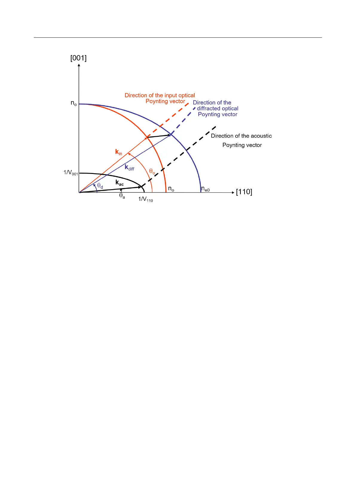
Figure 2.1: Phase-matching conditions and Poynting vector directions
~
k
diff,e
(ω
opt
) =
~
k
in,o
(ω
opt
) +
~
k
ac
(ω
ac
) (2.2)
Figure 2.1 shows the ordinary and extraordinary (optical) index curves for the birefringent
cystal as well as the acoustic slowness (inverse velocity) curve in the plane defined by the [001]
and [110] axes. The incident optical and acoustic wave vectors make respectively an angle θ
o
and θ
a
with respect to the [110] axes. The acousto-optic interaction is not collinear in terms
of wave vectors. The diffracted wave propagates along the extraordinary axis with an angle θ
d
(with respect to the [110] axis) given by the phase-matching conditions (Equation 2.2).
For given propagation directions of the optical and acoustic beams (θ
o
and θ
a
), the phase-
matching relationship can be viewed as an implicit equation which links acoustic and optical
frequencies. In thick crystals, this link is an almost one-to-one relationship (i.e. bijective)
between acoustic and optical frequencies. In other words, a single acoustic frequency diffracts
a single optical frequency.
2.1.2 Poynting vectors
In most acousto-optic modulators, a transverse acoustic wave interacts with the input optical
wave. The input optical Poynting vector is perpendicular to the acoustic one under the phase-
matching conditions. In the case of the AOPDF, the input optical and acoustic Poynting
vectors are collinear (Figure 2.1). The interaction is longitudinal (energy consideration) which
enables to maximize the interaction length between the two waves to obtain high spectral
resolution (section 2.2.2) and diffraction efficiency (section subsection 2.2.1). This also entails
the quasi-bijective relationship between acoustic and optical frequencies.
ω
ac
/ω
opt
= ν
ac
/ν
opt
= α(ω) (2.3)
V3.00 - 8
th
April 2019 (ContentsTable) (FiguresTable) 7/94