DAZZLER
TM
system manual Part I : installation & operation 4.2
C: A graph along with its legend, displaying influence of the different delays on global timing.
D: Some additional controls to change the triggering mode and to select the signals available
on the different output BNC sockets of the generator
7
. For more details concerning the
S1 and S2 output signals, please refer to subsection 8.7.3.
4.2.2 Key parameters
• Trigger to Laser represents the delay between the rising edge of the signal connected to
the trigger input of the RF generator and the optical event (e.g. Trigger to Laser =50µs
means that the laser pulse comes 50µs after the trigger edge). The Trigger to Laser control
MUST be adjusted by the user following the procedure described in subsection 4.2.3.
• T
p
mainly represents the propagation time of the acoustic pulse from the transducer to
its reflection upon the crystal input face. It corresponds to the delay between the RF
generation start and the acoustic wave reflection on the input face. Its value usually lies
between 3 and 15µs , depending on the Dazzler
TM
cut and the optical alignment. For
HR25 Dazzler
TM
systems, T
p
=7.5µs . It is advised not to change the default value set in
the software.
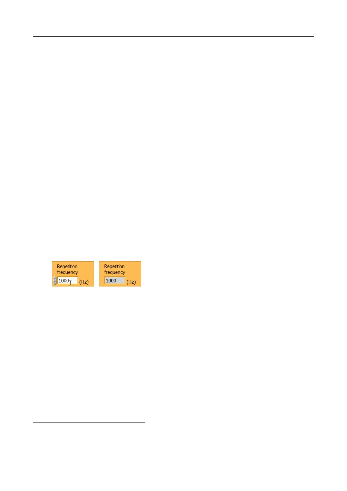
• Repetition Frequency is the frequency of the Trigger signal (Trigger input).
This numerical box can be either an indicator or a control. It is a control when Trigger
Mode selects Internal Source (variable duty cycle) and also when Trigger Mode
selects External Source and the parameters require Trig on Previous mode. The user
has to enter the exact value corresponding to the laser trigger source, see Figure 4.15 for
details.
(a) Control (b) Indicator
When an indicator, the box shows the actual Repetition
Frequency as counted by the RF generator (4.10(b)).
Figure 4.10: Different Repetition Frequency behaviors
When the Repetition Frequency item is a control, the input value may differ from the currently
measured value. If the measured value leads to significantly different computed timings, a
button appears (4.11(a)) to help copy the last measured value in the control and re-compute
timings. This copy can also always be obtained by the activation of the context menu (right-
click on the Repetition Frequency control, 4.11(b)), even if the button is hidden.
• TXtal represents the time needed by the acoustic pulse to propagate between the optical input
and output faces. Its value depends only on crystal cut and length, and cannot be modified
by the user. The Table 4.1 gives the typical values of TXtal for WB25, WR25 and HR25
Dazzler
TM
systems.
• Trigger Delay shows the computed optimal delay that will be introduced by the Dazzler
TM
RF
unit between the trigger rising edge and the RF generation start. Everytime any of the
above controls is modified, optimal Trigger Delay is re-computed and displayed.
7
S1 & S2 are always present, newer generators provide S1 to S4, either on the back panel or on the frontpanel
for rack mounted equipment.
V3.00 - 8
th
April 2019 (ContentsTable) (FiguresTable) 29/94