DAZZLER
TM
system manual Part I : installation & operation 4.3
Previous
trigger
Propagation (T
p
) Laser
Trigger Delay
Trigger to Laser
Acoustic signal
at input face
Trigger
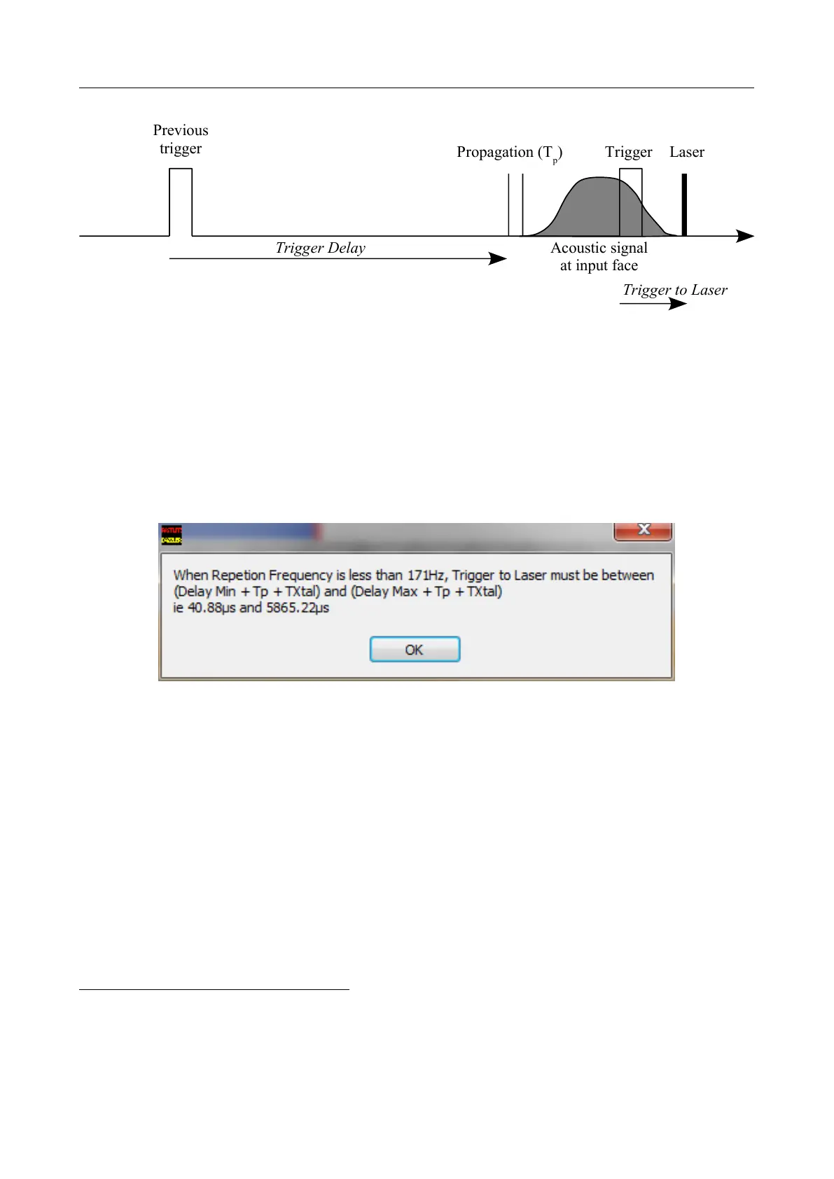
Figure 4.16: Timing in Trig on Previous mode
boards, it typically occurs for repetition rates below 171Hz. In this particular case, Equation 4.1
also leads to a Trigger to Laser maximum value :
Trigger to Laser
Max
= Trigger Delay
Max
+ T
p
+ T
Xtal
(4.3)
If one tries to input a greater value of Trigger to Laser , the Dazzler
TM
software outputs a
typical message displayed on Figure 4.17.
Figure 4.17: Trigger to Laser value out of range dialog (HR25 model typical values)
To reach a higher precision level than the one of the internal delay generator, the
Dazzler
TM
software adds or subtracts a delay to the spectral phase of the generated waveform.
For standard HR25 models with V5 boards, the precision is typically 0.18 µs. Because the
software uses the spectral phase of the generated waveform to reach this precision level, all
waveforms to be used have to be re-loaded after a change of the Trigger to Laser value
8
.
4.3.4 No Delay
If one needs to bypass the Dazzler
TM
RF generator delay circuits, this can be done by selecting
the “no delay” mode
9
(figure 4.18(a)). In this case, Trigger to Laser must be set to the measured
value and cannot be modified anylonger. An external delay generator must be used to provide
the trigger pulse to the Dazzler
TM
.
8
This affects particularly the sequences which are stored in the generator memories
9
This is the case for systems using the lowjitter option.
V3.00 - 8
th
April 2019 (ContentsTable) (FiguresTable) 33/94