DAZZLER
TM
system manual Part I : installation & operation 3.3
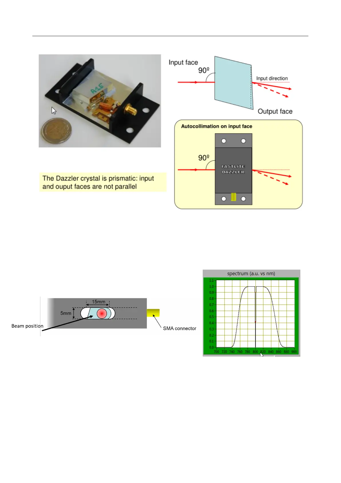
Figure 3.4: Details of the Dazzler crystal
3.3.1 Frequency Calibration
The Dazzler has qto be frequency calibrated to achieve accurate pulse shaping. Use an ampli-
tude spectrum with a narrow hole (example on Figure 3.6).
Figure 3.5: Beam position on the input face
Figure 3.6: Example of spectrum
with hole
Feed the diffracted beam into a well calibrated spectrometer. Verify the wavelength at which
the hole feature appears. If a difference dλ occurs with the programmed value and this difference
is significant (i.e. larger than 10nm), there is a setup problem, a non exhaustive list of possible
causes is:
• the input light polarisation orientation is incorrect
• the autocollimation is incorrect (e.g one degree error)
V3.00 - 8
th
April 2019 (ContentsTable) (FiguresTable) 20/94