DAZZLER
TM
system manual Part I : installation & operation 8.2
Note that the indicators are verified at each power up sequence: the indicators should blink 3
times slowly.
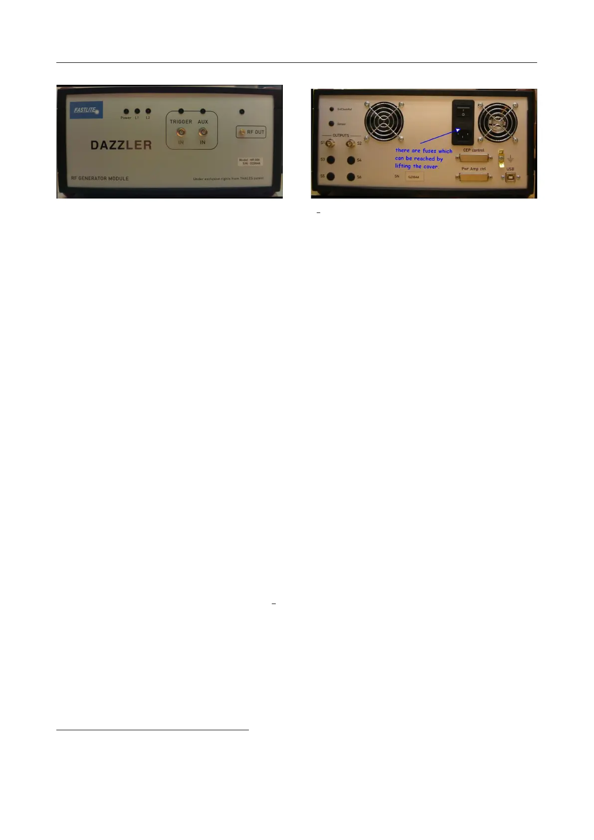
8.2.1 Power indicator
The P ower indicator monitors the 5V internal power supply and should be steady. If unlit,
check that the mains cord is correctly plugged to a live mains plug, check on the rear panel
that the fuses
2
are not blown: the power supply may be “damaged”.
8.2.2 L1 indicator
The L1 indicator is used to show the actual state of the microprocessor. In normal operation,
the LED is blinking at 1 Hz. It stops blinking if the microprocessor crashes. In this case, restart
the RF generator. Before switching off, if possible, zero the displayed waveform as required by
some RF amplifiers.
8.2.3 L2 indicator
The red L2 indicator signals alarm conditions: it blinks rapidly when an alarm condition has
been detected (see section 5.19). The normal condition is off or ”unlit”.
8.2.4 Trigger indicator
This is the LED just above the trigger in BNC input socket. This indicator will lit when
the trigger rate is measured after the generator goes succesfully online. It blinks at the trigger
rate under 100Hz and is steady above
3
.
8.2.5 AUX indicator
This indicator, just above the aux BNC plug, unlike trigger is not driven by a retriggerable
monostable circuit but by the buffered aux signal. It is unlit when the aux socket is empty,
2
with mains in the range 210V-240V use 2A slow blow when replacing
3
the LED is driven by a retriggerable monostable multivibrator 74xx123 set at 10ms
V3.00 - 8
th
April 2019 (ContentsTable) (FiguresTable) 79/94