DAZZLER
TM
system manual Part I : installation & operation 8.7
extracted from Siegman/PROD/.../DAZZLER/GZ0655.txt
signal usage RF board V5.x
GATEBASIG gating signal (option gating)
GENTRIG read trigger
GND LO level
HIWHENA hi when wave A is played
HWABUSY hwa.busy (option hwa)
HWASTROBE hwa strobe (option hwa)
MISSTRIG Trigger rate too fast(FIFO load)
PROTECTP protection period
QCLK quartz clock
S1SEQSYNC sequence synch (option seq)
S2SEQSYNC sequence synch (option seq)
SEQPARITY sequence: wavenumber is even (option seq)
T1OUT generate internal trigger
TPARITY trigger parity =ie.trigger/2 (reset by S7)
TRIGINA trigger block
VCC HI level
8.7.4 Descriptions of selectable signals
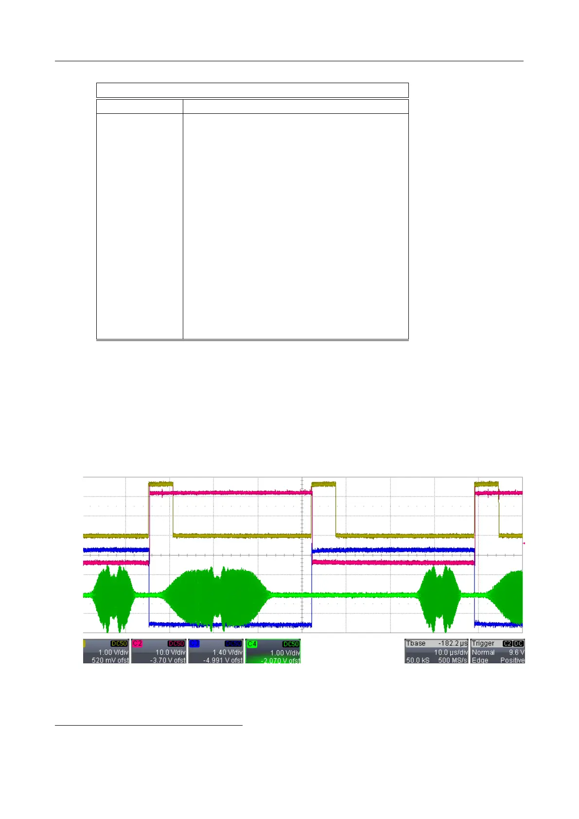
• hiwhenA ”high when wave A is played” is useful in alternate mode, or when waveform B
is selected and a high level is applied to the AUX terminal. Logic level LO corresponds
to waveform B, logic HI corresponds to waveform A. The tparity choice is based on the
triggers processed and not on the waveform selection.
traces: red = hiwhenA, yellow = trigger , green = RF, blue = tparity
• gate ”ON during RF signal” the gate signal is at high when the RF signal is generated:
it comes HI on the delayed trigger and goes to LO after the RF cycle has completed. It
comes slightly earlier than the RF signal
10
. /gate is negated gate.
10
the generation delay varies with the sampling frequency.
V3.00 - 8
th
April 2019 (ContentsTable) (FiguresTable) 88/94