DAZZLER
TM
system manual Part I : installation & operation 8.7
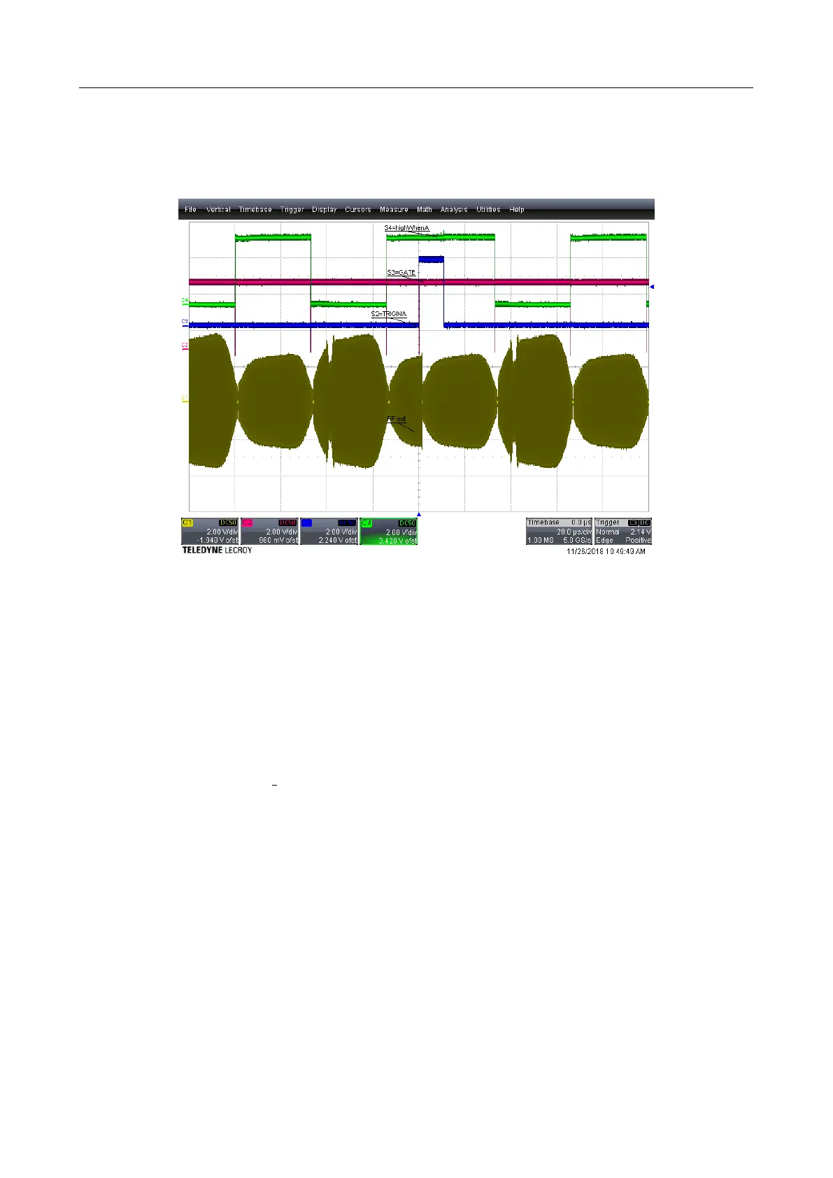
When both alternate and continuous are selected, generators with RF boards 5.x show the
pair of waveforms AB repeated continuously. Earlier generators repeated the same waveform
between triggers: many A and on trigger many B instead of many AB.
Figure 8.6: Alternate & Continuous mode
Details & Warnings:
• logic low selects waveform B, while logic high selects waveform A. If the BNC AUX is
unconnected, the signal is low,
• the auxcopy available on S1 eases debugging
• aux is sampled at the trailing edge of gate. A memory transfer from SRAM to FIFO is
initiated whenever a change in aux is detected. Using memory SRAM:
T ransferT ime = (T xtalxF data)x(3/80E6)x(33/32)
if T riggerP eriod < T ransferT ime there will””missed triggers”
It is also used to synchronize the sequences in burst mode.
8.7 Output signals S1-S4
These signals are defined by the hardware options purchased as well as the firmware loaded in
the generator. The signals available on your Dazzler
TM
system and their output assignment are
shown and selected by the software Trig&Mode panel. The list of available signals is revealed
by a click on the scroll control of each output.
V3.00 - 8
th
April 2019 (ContentsTable) (FiguresTable) 86/94