DAZZLER
TM
system manual Part I : installation & operation 5.1
The B indicator lights up when the wave stored in memory bank B is played. The graph shape
is similar to the time display discussed previously, except that its display is in the acoustic time
domain instead of the optical time domain, which leads to some distortion due to the following
factors :
1. spectral amplitude corrections for the RF analog response,
2. optional time corrections for the acoustic diffraction pattern,
3. optical dispersion of the ratio α between optical and acoustic frequencies leading to a non
linear correspondence between them.
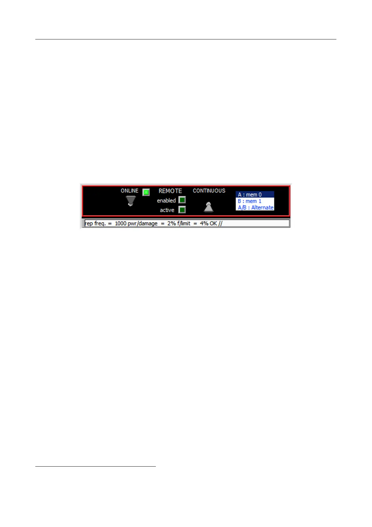
5.1.7 Machine controls
Figure 5.5: Machine Controls
The Machine Controls area contains indicators and switches to monitor and control the activity
of the RF generator.
When the ”online” switch is down (ie. offline), the software operates in ”offline mode” without
communicating with the RF generator: this is useful to prepare/simulate operations while not
connected to the generator.
When the ”online” switch is activated (ie. flipped up), communication with the RF generator
is initiated and if successful, the ”online” indicator lights, showing that the software operates
in ”online mode”. When in ”online mode”, the generator is periodically interrogated and the
result of this polling process is displayed in the poll message text line, see Figure 5.15. This
activity is shown in the message with the cycling every second of the last two characters between
the following: || \\ -- //.
The information shown is the actual trigger frequency
2
rounded to the lower integer and the
status with respect to acoustic damage. While this banner message is reflecting current opera-
tion values, a similar message banner below the spectrum and time graphs (subsection 5.1.5) is
showing values which would be obtained if the waveform defined by the current control settings
were to be loaded.
The ”remote enabled” indicator shows whether the system can be remotely controlled using
the text based interface (setup menu → remote enable option activated). The ”remote
active” indicator lights up in green every time a remote control request is being processed;
it lights up in red whenever there are errors in the remote control request. Please refer to
chapter 6.
2
The measurement is based on counting all triggers in a one second period.
V3.00 - 8
th
April 2019 (ContentsTable) (FiguresTable) 41/94