DAZZLER
TM
system manual Part I : installation & operation 5.1
polarization mode. With this setting, the Dazzler device is dispersion free, with the programmed
diffraction induced phase compensating the natural dispersion of the crystal.
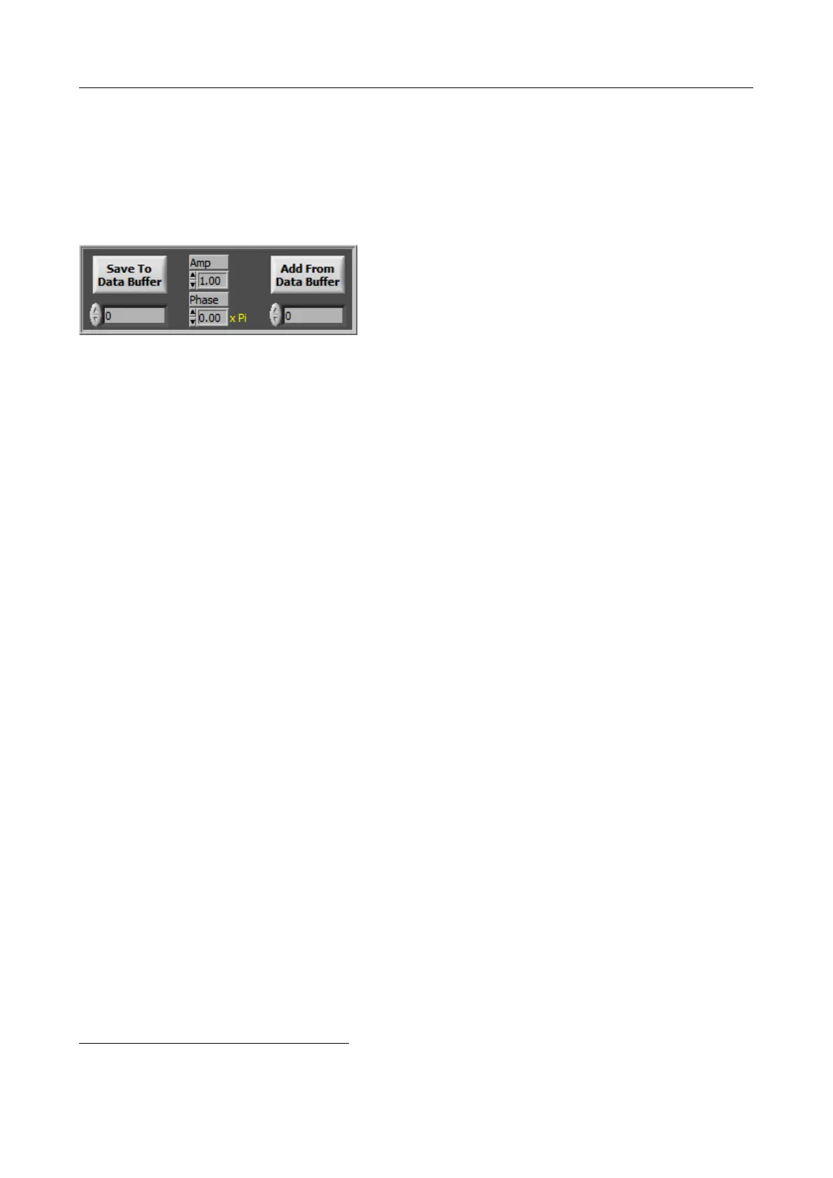
5.1.4 Grey Area : Waveform Combination
This panel is used to generate a waveform by the
arithmetic combination of the current waveform,
as defined by the current panel controls, and of
previously stored waveforms.
The current waveform may be stored in a data buffer
1
chosen by the index number below
the ”Save To Data Buffer” button, yielding S
saved
(ω). When the ”Add From Data Buffer”
button is not activated, the arithmetic combination is disabled: i.e the waveform is simply the
one defined by the panel controls A (ω) .e
i·φ(ω)
. When the ”Add From Data Buffer” button is
activated, the resulting waveform is computed as:
S(ω) = A(ω) · e
i·φ(ω)
+ a · e
i·π·φ
· S
saved
(ω)
where S
saved
(ω) is the signal saved in the memory buffer defined below the ”Add From Data
Buffer” button. The values of the ”Amp” (for Amplitude) and ”Phase” controls correspond
respectively to a and φ in the above formula (see section 2.3).
For example, in order to generate two identical pulses separated by a given delay, proceed as
follows :
1. set the parameters for a single pulse
2. press the save button with the memory buffer value set at 0
3. shift in time by changing the delay in the green area
4. set the ”Amp” control at 1 and the ”Phase” control at 0
5. press the ”Add From Data Buffer” button with the memory buffer value set at 0
To create a third pulse, continue as follows :
6. press the save button with the memory buffer value set at 1
7. deactivate the add waveform button
8. shift in time by changing the delay in the green area
9. press the ”Add From Data Buffer” button with the memory buffer value set at 1
5.1.5 Graphs
Spectrum (a.u. vs nm)
This graph represents the amplitude response of the filter (|H(ω)| defined in section 2.1.3). It
shows out two curves: one black (smooth) which represents the programmed spectral amplitude,
1
program internal memory, not to be confused with the hardware generator internal memory slots
V3.00 - 8
th
April 2019 (ContentsTable) (FiguresTable) 39/94