FS10 Series
22 Fluid Components International LLC
FS10 Field Quick Setup Procedure
Select desired setup option A or B below by pressing the (-) or (+) button continuously for the designated time period. In either case, the ability to set
up the device in actual flow conditions is required, i.e., actual switch point flow rate, or flow close to intended value (Mode A) or actual zero flow and
full scale flow (Mode B). In both cases, setting of the fail-safe is also established and the final switch (alarm) point can be adjusted in 5% of span
increments before exiting to normal operation.
• Enter into Mode A to capture actual switch point and assume default settings for the flow range
OR
• Enter into Mode B to set actual range (Zero and Full Scale) and a default switch point
Table 3 – Mode Operation Summary
MODE A – SWITCH POINT CAPTURE: Captures Switch Point and Sets Default Range
Button
Press &
Hold
LED Pattern
1
Setup
Press Momentarily To
Capture And Exit
2
After Release, 5 sec. to:
(–) minus
For gas,
low flow
liquids.
6 to 9
seconds
Blinking
Throttle flow to
desired switch
point setting.
(–) Captures switch point,
exits fail-safe Low
Press (–) or (+) button momentarily to
step captured switch point down or up
in 5% increments
(+) Captures switch point,
exits fail-safe High
(+) plus
For liquids,
high flow
gases.
6 to 9
seconds
Blinking
Throttle flow to
desired switch
point setting.
(–) Captures switch point,
exits fail-safe Low
Press (–) or (+) button momentarily to
step captured switch point down or up
in 5% increments
(+) Captures switch point,
exits fail-safe High
MODE B – SPAN SETTING: Captures Zero & Full Scale and Sets Default Switch Point
Button
Press &
Hold
LED Pattern Setup
Press Momentarily to
Save and Exit
2
After Release, 5 secs. to:
(–) minus
For gas,
low flow
liquids.
Greater
than 10
seconds
LEDs sequence down
from 3 to 1 and LEDs 8
to 10 sequence up
Throttle flow over
operating range to
capture zero and
full scale setting.
(–) Sets the flow range
and exits fail-safe Low
Press (–) or (+) button momentarily to step
switch point down or up in 5% increments
from the default setting of 30% of span
[exiting (–) button; fail-safe Low] or 70% of
span [exiting (+) button; fail-safe High].
(+) Sets the flow range and
exits fail-safe High
(+) plus
For liquids,
high flow
gases.
Greater
than 10
seconds
LEDs sequence down
from 3 to 1 and LEDs 8
to 10 sequence up
Throttle flow over
operating range to
capture zero and
full scale setting.
(–) Sets the flow range
and exits fail-safe Low
Press (–) or (+) button momentarily to step
switch point down or up in 5% increments
from the default setting of 30% of span
[exiting (–) button; fail-safe Low] or 70% of
span [exiting (+) button; fail-safe High].
(+) Sets the flow range and
exits fail-safe High
1. LEDs blink when entering these modes. Blink rate increases when button is released, indicating mode is active and flow is ready for
capture by momentary press of (–) or (+) button.
2. Refer to fail-safe default settings and span default settings below for complete description of exit parameter settings.
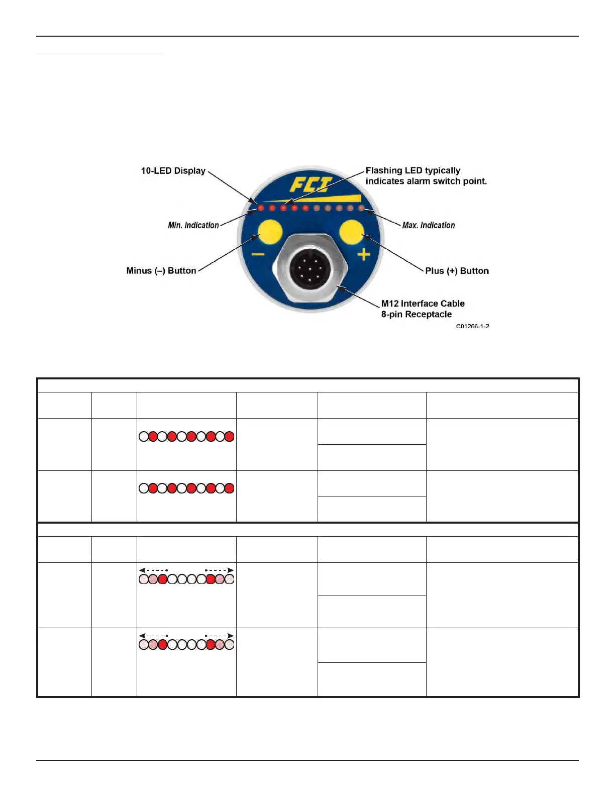
Figure 3 – FS10 Button/LED Panel