FS10 Series
2 Fluid Components International LLC
2 INSTRUMENT INSTALLATION
The FS10 is marked with a flow direction arrow or “A” etched onto the sensor element. It is located on the flattened area of the sensor body
close to the housing or on the assembled tee. For 1/4 and 3/8 inch tube tees, mount the instrument with the “A” upstream of the flow to maximize sensi-
tivity at low flow rates (flow into the “A”). Larger line sizes should follow the flow arrow direction. Refer to Figure 1. Where the flow tube is not included
with the sensor assembly, the orientation mark must be parallel to flow (±3°). For liquid vertical flows in particular, FCI recommends the sensor ele-
ment be installed where flow is in the up direction. In vertical low flow gas applications, flow in the down direction is recommended.
As a level device, the orientation mark can be perpendicular or parallel to the liquid level. The sensor element may be installed top mount 90° to the
liquid surface. The sensor element can be at any angle as long as the flow direction follows the flow arrow. Liquid applications where the flow ele-
ment is positioned other than horizontally, FCI recommends the flow go in the up direction.
Caution:
To minimize the possibility of damage, leave the protective covers over the sensing area in place until the time of installation.
Take extra precaution with the sensing elements and surface when installing.
For NPT process connections: Apply the appropriate sealant compatible with the process media to the male threads. Tighten until the orientation
mark is positioned correctly. Check for leaks.
Note
: ATEX/IEC labeled units are supplied with a UV filter disc located inside the silicone boot. The disc can be removed if the
display is not subjected to UV light (e.g., sunlight, mercury-vapor lighting, etc.). See “Installation Details, FS10 Silicone Boot
and UV Filter” on page 19 for UV filter disc removal details.
Special Conditions for Safe Use
a. Provisions shall be made to prevent the rated voltage being exceeded by transient disturbances of more than 40%.
b. For applications in explosive atmospheres caused by air/dust mixtures, cable and conduit entries used shall provide a degree of ingress
protection of at least IP 54 according to EN 60529.
c. When the temperature under rated conditions exceeds 158 °F [70 °C] at the cable or conduit entry point, or 176 °F [80 °C] at the branching
point of the conductors, the temperature specification of the selected cable shall be in compliance with the actual measured temperature.
d. Cable gland assemblies are factory tightened – do not adjust; M12 connectors assembled finger-tight. Mencom MDC-8MR-PG9 or equal
M12 connector is used on FS10.
e. Parts of the enclosure are non-conducting and exceed the maximum permissible resistance according to IEC 60079-0. Therefore, to avoid
electrostatic charge build-up, it must not be rubbed or cleaned with solvents or a dry cloth when installed/used within a potentially
explosive atmosphere.
Remote Flow Element Installation Into Zone 1, Division 1 Areas
Refer to Probe Installation, Operation & Maintenance manual (06EN003428) for Zone 1/Division 1 installation.
1 INSTRUMENT DESCRIPTION AND IDENTIFICATION
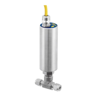
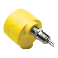
The FS10 Series is a universal flow monitor and switch specifically designed for gas and liquid process analyzer sampling systems. The FS10A is a fast re-
sponding, highly repeatable sensor which installs easily into a standard tube tee fitting or SP76 (NeSSI) modular manifold. The FS10i is an insertion type
instrument with ¼-inch or ½-inch NPT fitting (fixed 2- or 4-inch length) or ½-inch NPT compression fitting (6-inch length, Teflon or stainless steel ferrule).
FLOW