FS10 Series
Fluid Components International LLC 23
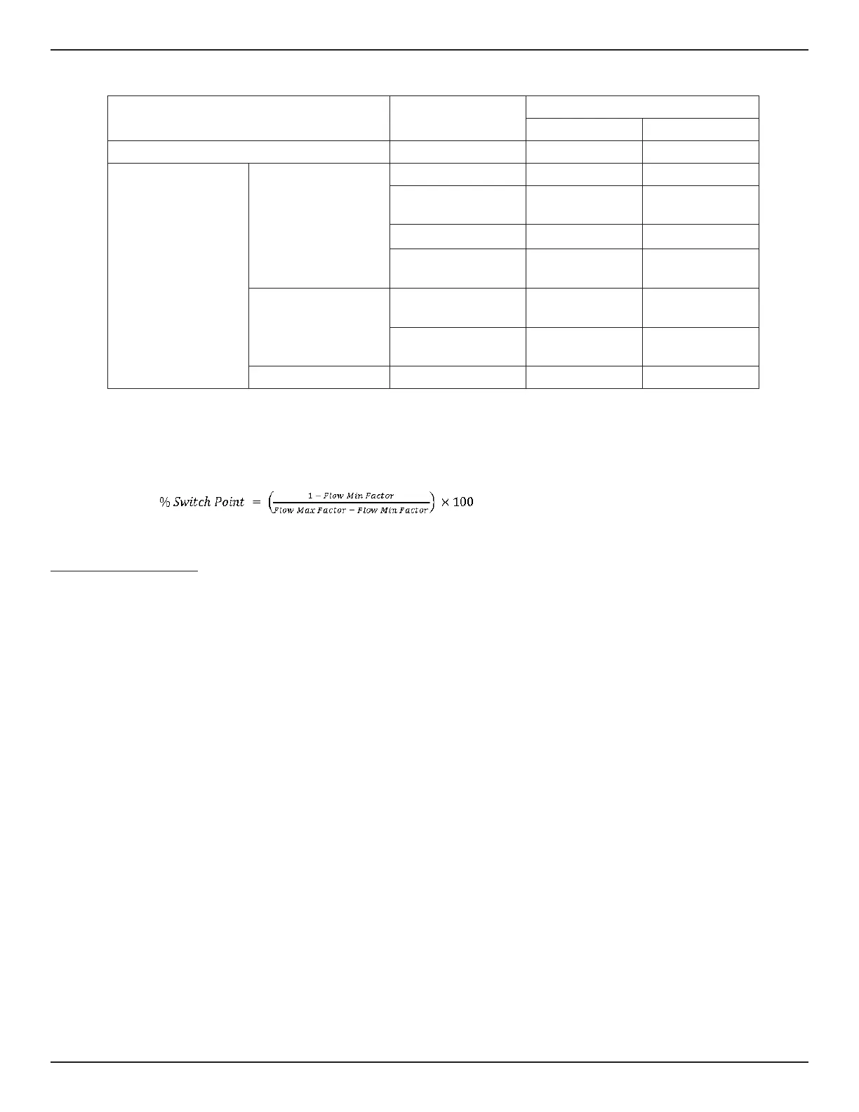
Parameter
Button Selection (Default Settings
3
)
(–)
3
(+)
3
Initial Button Press: Enter Function Mode (A or B)
Bank Selection
1,2
1 3
2nd Button Press: Exit
Function Mode
Common to Mode A
and Mode B
Fail-safe Low High
Hysteresis Relative to
Switch Point
Above Below
NAMUR Low High
Relay Trip Adjust - Step
Value
5% 5%
Mode A Only
Flow Min Factor Around
Switch Point
4
0.5 0.1
Flow Max Factor Around
Switch Point
4
2 1.5
Mode B Only
Switch Point 30% 70%
Notes: 1. Bank 2 is always set to the low heater setting, Bank 4 is always set to the high heater setting (same as banks 1
and 3 respectively).
2. (–) and (+) buttons can be set to represent Bank 2 or 4 with additional set parameters in place.
3. Additional defaults may be applied using PC interface; e.g., time delays, hysteresis setting, filter value; and then
saving to Bank 2 or 4.
4.
Table 4 – Quick Setup Mode Defaults
Quick Setup Mode Summary
Single button operation is used in both Mode A and Mode B.
Use either mode to set the default fail-safe and fine tune the switch point.
For either mode:
• The minus (–) button represents Bank 1 (low heater setting) for gas and low velocity liquids
• The plus (+) button represents Bank 3 (50% greater heater setting) for liquids and high velocity gas
As appropriate to the process media press and hold (–) minus or (+) plus button continuously to start Quick Setup Mode (QSM).
Mode A: Capture Switch Point + Set Default Zero & Full Scale
1. After 6 seconds, every other LED will blink, indicating you have entered the capture switch point mode. If desired, release button to
enter this setup option. The LEDs then blink faster to acknowledge Capture Switch Point ready.
2. Throttle flow rate to where desired switch point is to be set. Wait at least 30 seconds to ensure unit has a stable signal.
3. Momentarily press (–) button (fail-safe low) or (+) button (fail-safe high) to capture switch point and exit.
• Fail-safe exit low (–) minus: Span is set at 2 times switch point value; Zero is set at ½ switch point value
• Fail-safe exit high (+) plus): Span is set at 1.5 times switch point value; Zero is set at 1/10 switch point value
Unit pauses for 5 seconds then returns to normal operating mode.
4. Immediately after exiting from this mode, the LED representing the switch point blinks rapidly for 5 seconds. During this time the user can incre-
ment or decrement the switch point setting in 5% intervals of the newly established span using the (+) and (–) buttons. After 5 seconds from the
last button press the unit reverts to normal operating conditions and the LED blinks normally in its new switch point location (if moved).