FS10 Series
Fluid Components International LLC 1
Instrument
Media Compatibility
All gases and liquids compatible with 316L stainless steel and Hastelloy C22.
Process Connection
FS10A: ¼" NPT; compatible with ¼", 3/8" and ½" tube tee,
¼" tube tee with 1/8" injection tube adapters and SP76 adapter (FCI
part number 019897-01)
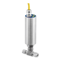
FS10i: ½" male NPT compression fitting with 316 SST or Teflon ferrule
¼" male NPT 316 SST (2-inch [50 mm] fixed length)
Flow Sensitivity/Range
Air: 0.25 to 400 SFPS [0,076 to 0,15 MPS]
Water: 0.01 to 0.5 FPS [0,003 to 0,15 MPS]
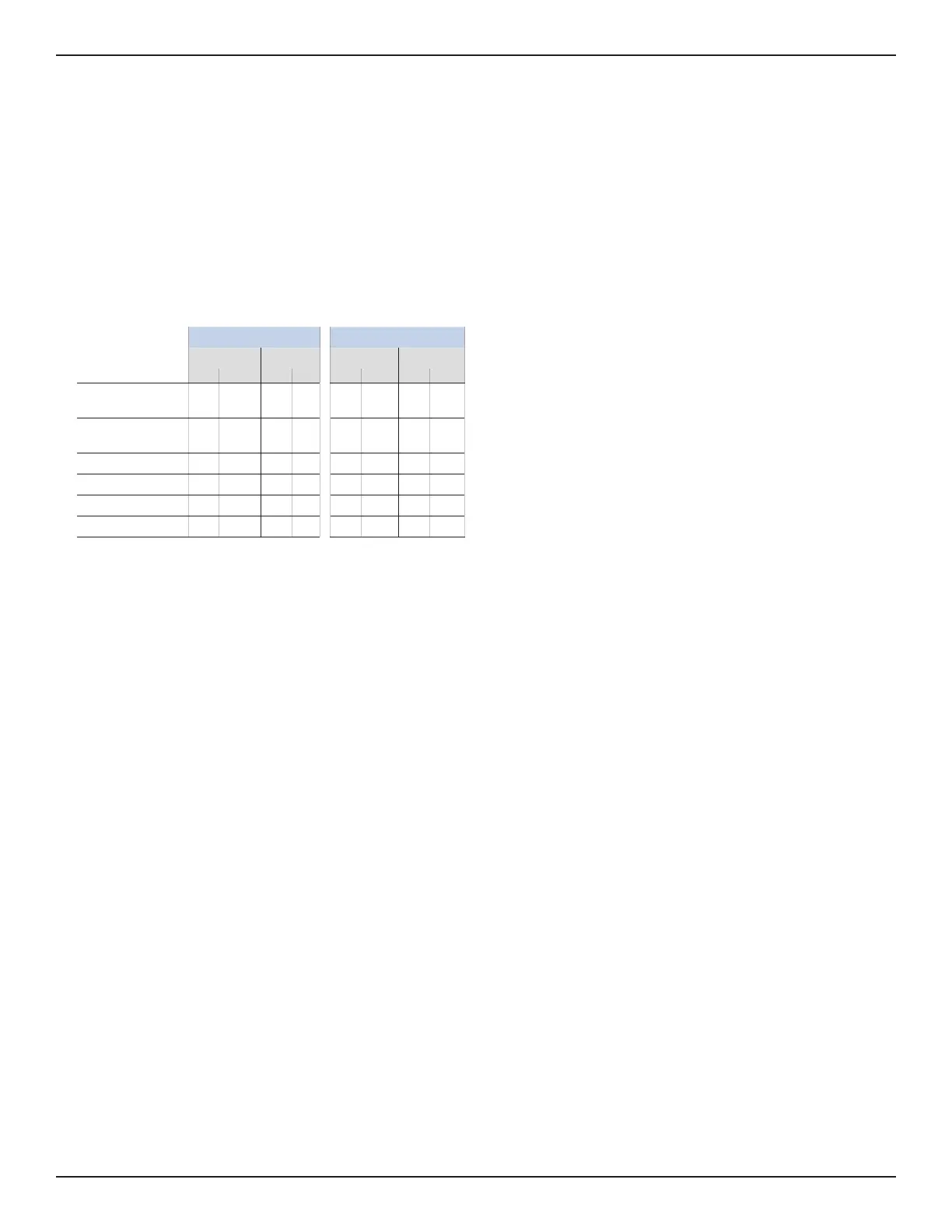
Air / Gas Liquids
CC / Min SCFH CC / Min GPH
Min Max Min Max Min Max Min Max
1/8” tube adapter with
0.0625” ID injection tube
10 2,000 0.02 5 0.70 18.00 0.01 0.30
1/8” tube adapter with
0.0940” ID injection tube
25 5,000 0.05 10 1.50 40.00 0.03 0.60
1/4” tube tee 50 20,000 0.10 40 4.00 100.00 0.07 1.70
SP76 adapter 50 20,000 0.10 40 4.00 100.00 0.07 1.70
3/8” tube tee
180
50,000 0.40 100
14.00
350.00 0.20 5.50
1/2” tube tee
375
100,000 0.80 200
30.00
750.00 0.50 12.00
Repeatability
± 0.5% of reading
Temperature Coefficient
For temperatures > ±30 °F [±16 °C]
Gas: Maximum ±0.025% of reading/°F up to 500 °F
[±0.05% of reading/°C up to 260 °C]
Liquid: Maximum ±0.2% of reading/°F up to 250 °F
[±0.367% of reading/°C up to 121 °C]
Turndown Ratio: 5:1 to 100:1
Agency Approvals
Integral Electronics
FM, FMc: Nonincendive, Class I Division 2 Groups A, B, C, D;
Class II, Division 2 Groups E, F, G; Class III,
T4@Ta=71°C Type 4X
ATEX, IEC: Nonincendive for gas and dust, Zone 2
II 3 G Ex nA IIC T4 Gc, -40 °C ≤ Ta ≤ +71 °C
II 3 D Ex tc IIIC T 81°C Dc, -40 °C ≤ Ta ≤ +71 °C
IP64
Ingress Protection: IP65, IP66, IP67 in non-hazardous locations.
CE Marking, CRN, complies with Canadian Electrical code requirements of
ANSI/ISA 12.27.01-2011 as a single seal device.
IEC 61508 (SIL): SIL 2 compliant; Safe Failure Fraction (SFF) 90%
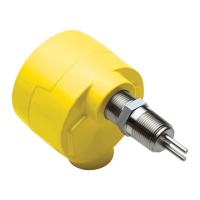
Remote Flow Element
FM, FMc: Class I, Division 1, Groups A, B, C, D; T2...T6
Ta = -40 °C TO +65 °C (Electronics)
Class II/III, Diviison 1 Groups E, F, G; T2...T6
Ta = -40 °C TO +65 °C (Electronics); Type 4x, IP67
Tp = -40 °C TO 260 °C (T1...T6) Includes Div1/Zone1 ambient
temperature zone.
ATEX: II 2 G Ex d IIC Gb T2....T6; Ta = 40 °C TO +65 °C
II 2 D Ex tb IIIC Db T300 °C...T85 °C; IP67
IEC: Ex d IIC Gb T2....T6; Ta = 40 °C TO +65 °C
Ex tb IIIC Db T300 °C...T85 °C; IP67
Refer to Probe Installation Operation manual [06EN003428] for
Zone 1/Division 1 installation.
Flow Element
Materials of Construction (wetted parts) 316L stainless steel with Hastelloy
C22 thermowells; optional, all Hastelloy C22 probe assembly
Operating Temperature
Standard: -40 °F to 250 °F [-40 °C to 121 °C]
FS10i, Teflon ferrule: -40 °F to 200 °F [-40 °C to 93 °C]
Electronics limited to 160 °F [71 °C]
Remote probe with polyurethane cable limited to 194 °F [90 °C]
Medium Temp: -40 °F to 500 °F [-40 °C to 260 °C]; remote configuration
only - probe and Teflon jacketed cable.
Operating Pressure
Tube tee and insertion: 2000 psig [138 bar(g)]
FS10i, Teflon ferrule: 150 psig [10 bar(g)]
SP76 adapter: Per SP76 manifold specifications up to 500 psig
[34 bar(g)] maximum
Remote flow element; IP67
Transmitter/Electronics
Enclosure
NEMA 4X [IP64], CE rated (Div 2, Zone 2 areas)
IP64, IP65, IP66, IP67 in non-hazardous locations
Operating Temperature
-40 °F to 160 °F [-40 °C to 71 °C]
Output Signals
Standard:
(1) Relay (SPDT, 1A @ 24 VDC); [1A @ 24 VDC/120 VAC, FM and FMc only]
or (1) Open Collector N-Channel MOSFET (100 mA);
(1) 4-20 mA* (500 Ω max. load). User scalable, general purpose, uncali-
brated output proportional to flow rate for trend monitoring.
(1) RS232C Serial I/O
(For linearized, calibrated analog outputs see FCI thermal mass flow meter
products)
* Fault indication per NAMUR NE43 guidelines, user selectable high (>
21.0 mA) or low (< 3.6 mA)
Display
10 LED array, red; sequential lighting proportional to flow trend and flashes
at setpoint
User Interface
Two top-mounted push buttons to program switch point, zero and span set-
ting, relay hysteresis and time delay; button operation may be user disabled
to prevent unwanted changes; all set-up functions also programmable via
RS232C port
Input Power
24 VDC (21.5 VDC to 30 VDC); maximum 2.5 watts
Remote Configuration
Transmitter/electronics may be remote-mounted from flow element using
interconnecting cable; remote flow element available with
potted cable in 6’, 15’ or 30’ [2 m, 5 m or 10 m] length and M12 connection
plug at electronics; optional extended temperature service to 500 °F [260 °C]
with selection of PTFE jacketed cable.
TECHNICAL SPECIFICATIONS