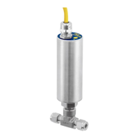
FS10 Series
30 Fluid Components International LLC
Function #
Function
Name
LED Pattern
0 = LED OFF
1 = LED ON
Parameter
LED Pattern for
Parameter
Description
1
Switch Point
Adjust
1000000000
- +
RELAY_LIMIT
1 – indicates current
value relative to full
scale
Button controls adjust relay switch point
in 10% increments.
2
Switch Point
Capture
1100000000
- +
RELAY_LIMIT
1 – indicates current
value relative to full
scale
When entering this function the ready-
to-capture LED pattern is presented
(0101010101). Pressing either button
precisely captures the current flow value
as the new relay switch point.
3 Fail-safe
1110000000
- +
RELAY_POLAR
0000011111 = ON
above (default)
1111100000 = ON
below
Selects whether the relay is ON (ener-
gized) if the flow value is above the relay
switch point, or if the relay is ON (ener-
gized) when the flow value is below the
relay switch point. Pressing the buttons
toggles between the two options (default
= ON above switch point – typical for low
flow alarm).
6
Minimum
Flow Cap-
ture
1111110000
- +
CUST_FLOW_MIN
1 – indicates current
value relative to full
scale
When entering this function the ready-
to-capture LED pattern is presented
(0101010101). Pressing either button
captures the current flow value as the
new display zero point.
7
Maximum
Flow Cap-
ture
1111111000
- +
CUST_FLOW_MAX
1 – indicates current
value relative to full
scale
When entering this function the ready-
to-capture LED pattern is presented
(0101010101). Pressing either button
captures the current flow value as the
new display maximum flow point. Note:
This mode is only valid if the DISPLAY_
RANGE_MODE (5) is “static.”
8
Hysteresis
Applied
Above
or Below
Switch
Point
1111111100
- +
RELAY_HYSTERESIS_
EFFECT
0000011111 = apply
above
1111100000= apply
below
Selects whether the hysteresis is to be
applied above (default) or below the
relay switch point. Pressing the buttons
toggles between the two options.
9
Maximum
Hysteresis
Value
1111111110
- +
RELAY_HYSTERESIS
1 – indicates current
value relative to
maximum 10%
hysteresis (MAX_
HYSTERESIS)
Buttons adjust the value of the dead
band effect. Increments in 1 percent
of switch point value. Default setting
is 2% of span. Button range 0-10%.
Wider range available through RS232
interface.
10
Time Delay
to Activate
Relay or
Binary Pulse
1111111111
- +
RELAY_TURN_ON_
DELAY
1 – indicates current
value relative to
maximum delay
(MAX_DELAY)
Time delay from when flow measurement
is greater/less than relay switch point, to
turn on relay. Increments and decrements
in 1 second steps [max. default setting 10
seconds when using buttons].*
Table 7 – Button Controls