63
MAINTENANCE
Air filters
Checking the filters is considered routine maintenance to be carried out according to the place where the unit is installed. It is
advisable to carry out this operation weekly in particularly dusty places. All the units are fitted standard with pleated filter cells
(G4 filtering class according to EN 779) having standard dimensions in order to be available from any manufacturer or dealer. For
greater safety it is advisable to install, as an accessory, the differential pressure switch for indicating dirty filters.
The filter section in the unit differs for its position in the respective construction configurations.
• In the standard configuration (VB) the filter section is located on the outside of the unit, suitably inserted in a special frame
applied on the inlet. To clean the filters, proceed according to the instructions given below.
1. Remove the prefilter frame closing side panel by loosening the special knurled wheels.
2. Remove the filters positioned on special guides.
3. Wash the filtering mat in lukewarm water and a normal detergent.
4. Rinse thoroughly under running water.
5. Dry the filtering baffles thoroughly and refit them in the special seats.
6. Use a screwdriver to loosen the self-tapping screws joining the upper filtering cell to the lower, if replacement is necessary.
• In the other construction configurations available the filter section is located inside the unit, in the air mixing chamber of
the additional module. For access and normal cleaning, remove the relevant foam panel.
1. Remove the filter inspection foam panel by undoing the closures a ¼ turn with the special triangular wrench provided.
2. Remove the standard filters positioned on special guides. Make sure to periodically check the state of the G4 pleated cells
and carry out cleaning as described above or replacement when necessary. These operations are all-important also for
better filtering efficiency of any rigid pocket filters present, and to increase the time intervals between replacing.
3. Check the state of any rigid pocket filters present and replace whenever necessary, using a screwdriver to loosen the self-
tapping screws joining the upper filtering cell to the lower with special restraint guides.
4. Fit the filter inspection panel in its seat before starting the unit.
Transmission
To meet most installation needs the double suction centrifugal fans fitted on the unit are coupled to electric motors with a transmis-
sion system consisting of a belt, electric motor, fixed fan pulley and expanding motor pulley. All the components, sized for reliability
and low maintenance, in any case require periodical checking in order to avoid possible extraordinary maintenance.
Belts
Check the alignment of the belts with the motor and fan pulleys. For the expanding pulleys always refer to the centre of the groo-
ves and not the edge of the pulleys. Loosen the bolts fixing the motor feet and move them along the slots in the slide until obtaining
correct alignment. If the ends of the slots are reached, also shift the slide along the fixing supports. Make sure the belt has not lifted
and that it does not touch the bottom of the pulley grooves and, whenever two are provided for, that their lengths are equal. Check
correct belt tension. Insufficient tension causes slipping, with consequent overheating and a significant shortening of its useful life.
On the other hand, excessive tension subjects the belt to greater stresses than those permissible, with consequent reduction in
its life, excessive strain on the supports and a reduction in bearing operation hours.
Belt tension can be varied by means of the worm screw of the slide, on which the electric motor is positioned, using a socket
wrench or spanner. If specific instruments are not available for measuring the tension of the belts, the following approximate me-
thod can be used.
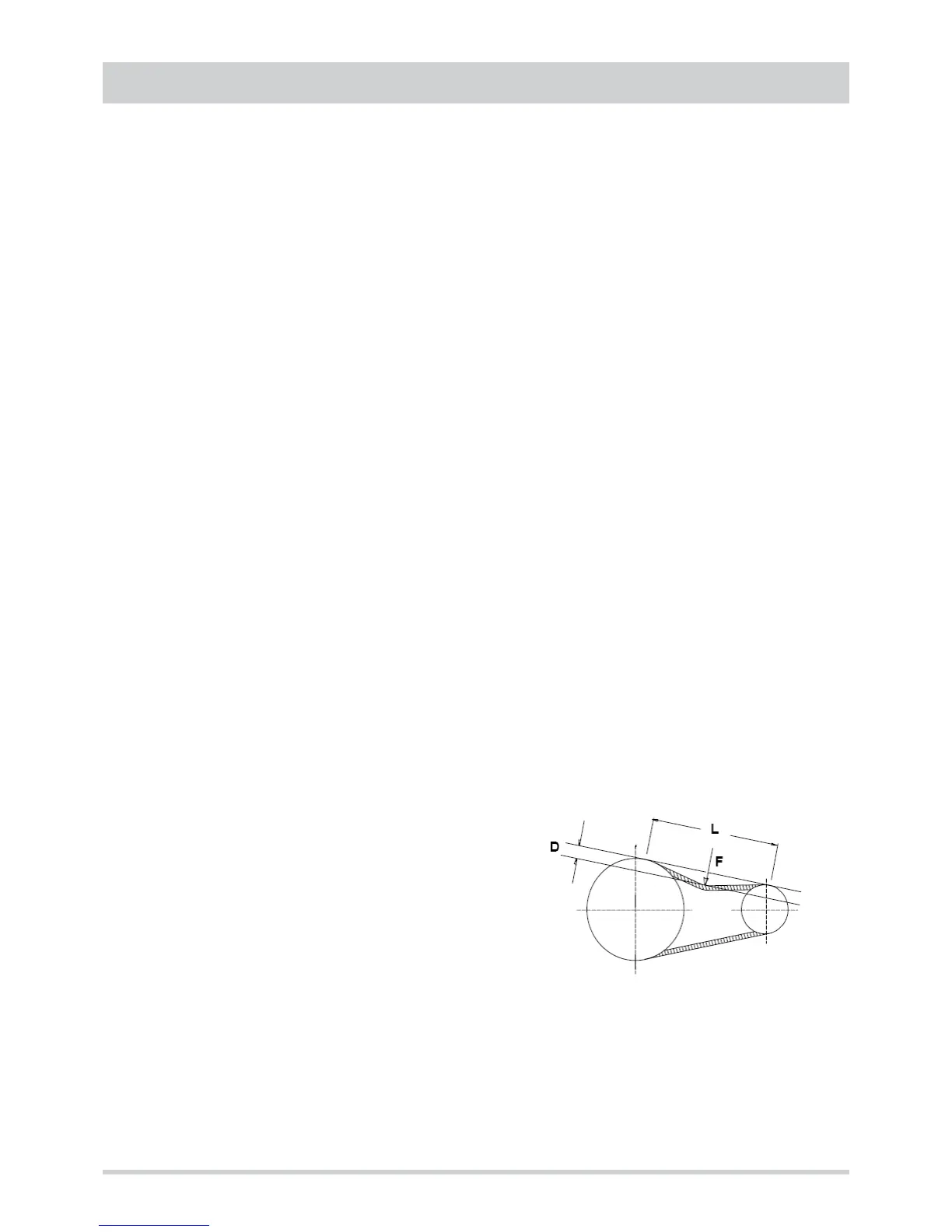
Measure the free section L, for each belt.
Using a torque wrench, apply a perpendicular force F in the middle of L able to cause a deflection D of 1.5 mm for every 100 mm
of length L.
Make sure the applied force F is approx. 35-40 N.
• L = pulley centre distance [mm]
• F = force [N]
• D = elastic deviation [mm]
D = L x 0.015