2 CANopen [X4]
Festo – GDCP-CMMP-M3/-M0-C-CO-EN – 1510b – English 17
2.4.1 Setting the node number via DINs and FCT
Each device in the network must be assigned a unique node number.
The node number can be set via the digital inputs DIN0 … DIN3 and in the FCT programme.
Permissible values for the node number lie in the range 1 … 127.
Setting the offset of the node number via DINs
The node number can be set via the circuitry of the digital inputs DIN0 … DIN3. The offset of the node
number set via the digital inputs is displayed in the FCT programme on the “Fieldbus” panel in the “Op
erating parameters” tab.
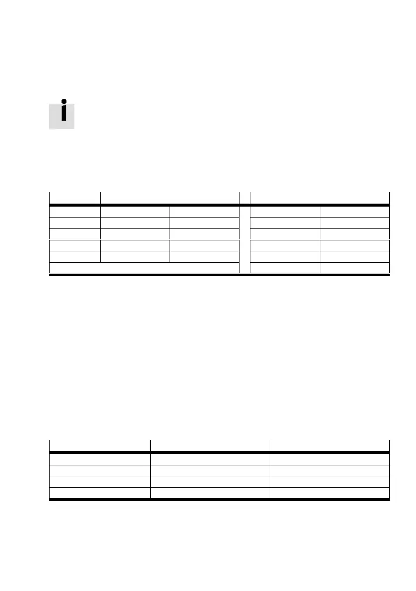
DINs Value Example
High Low Value
0 1 0 High 1
1 2 0 High 2
2 4 0 Low 0
3 8 0 High 8
Total 0 … 3 = node number 0 … 15 11
Tab. 2.7 Setting the node number
Setting the base address of the node number via FCT
The base address of the node number can be set via FCT on the “Fieldbus” panel in the “Operating
parameters” tab.
The resulting node number is dependent on the option “Fieldbus parameterisation via DINs” on the
“Application data” page. If this option is activated, the node number is determined by adding the base
address in the FCT to the offset via the digital inputs DIN0…3.
If the option is deactivated, the base address in the FCT corresponds to the resulting node number.
2.4.2 Setting the transmission rate via DINs or FCT
The transmission rate can be set via the digital inputs DIN12 and DIN13 or in the FCT.
Setting the transmission rate via DINs
Transmission rate DIN 12 DIN 13
125 [Kbit/s] Low Low
250 [Kbit/s] High Low
500 [Kbit/s] Low High
1 [Mbit/s] High High
Tab. 2.8 Setting the transmission rate

 Loading...


