3 CANopen access procedure
Festo – GDCP-CMMP-M3/-M0-C-CO-EN – 1510b – English 37
3.5.2 Structure of the EMERGENCY Message
When an error occurs, the motor controller transmits an EMERGENCY message. The identifier of this
message is made up of the identifier 80
h
and the node number of the relevant motor controller.
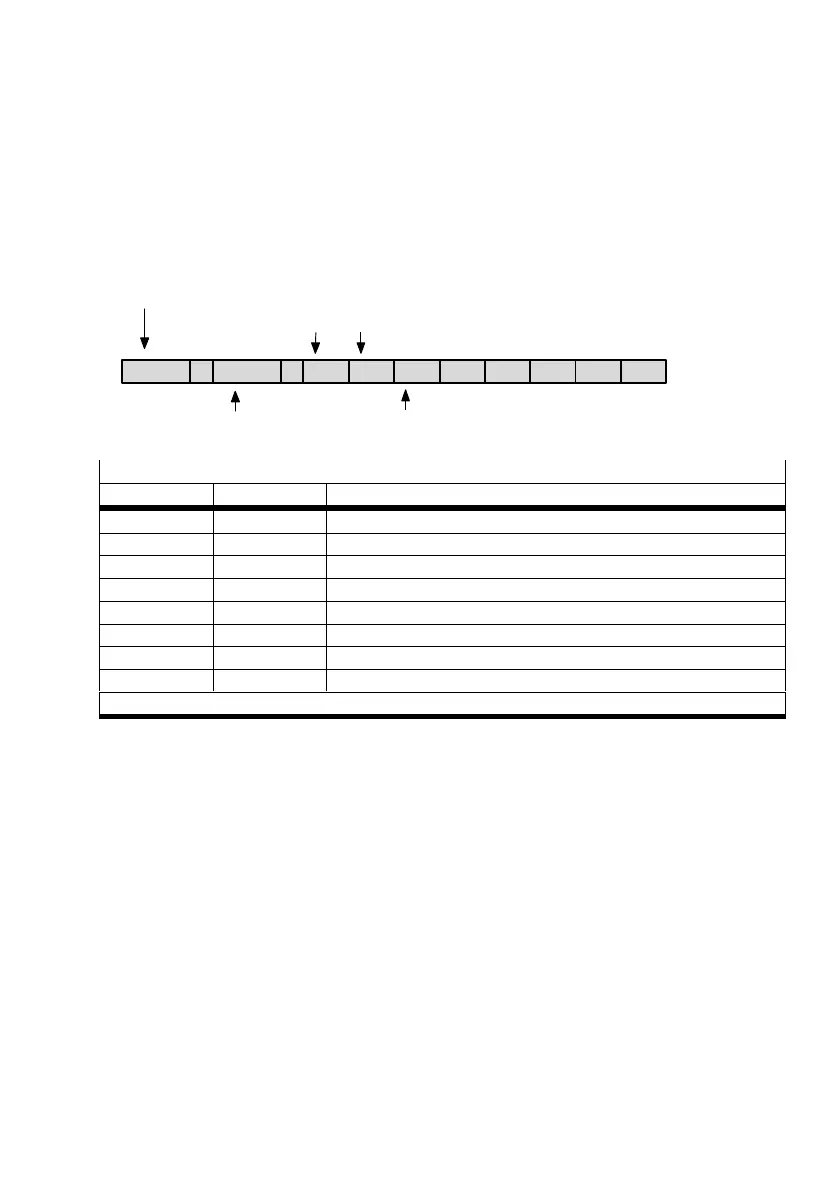
The EMERGENCY message consists of eight data bytes, whereby the first two bytes contain an
error_code, which is listed in the following table. An additional error code is in the third byte
(object1001
h
). The remaining five bytes contain zeros.
81
h
8 E0 E1 R0 0 0 0 0 0
Identifier: 80
h
+ node number
Error_code
Data length Error_register (obj. 1001
h
)
error_register (R0)
Bit M/O1) Significance
0 M generic error: Error is present (Or-link of the bits 1 … 7)
1 O current: I
2
t error
2 O voltage: voltage monitoring error
3 O temperature: motor overtemperature
4 O communication error: (overrun, error state)
5 O –
6 O reserved, fix = 0
7 O reserved, fix = 0
Values: 0 = no error; 1 = error present
1) M = required / O = optional
Tab. 3.9 Bit assignment error_register
The error codes as well as the cause and measures can be found in chapter B “ Diagnostic messages”.
3.5.3 Description of the Objects
Object 1003
h
: pre_defined_error_field
The respective error_code of the error messages is also stored in a four-stage error memory. This is
structured like a shift register, so that the last occurring error is always stored in the object 1003
h
_01
h
(standard_error_field_0). Through read access on the object 1003
h
_00
h
(pre_defined_error_field), it
can be determined how many error messages are currently stored in the error memory. The error
memory is cleared by writing the value 00
h
into the object 1003
h
_00
h
(pre_defined_error_field_0). To
be able to reactivate the output stage of the motor controller after an error, an error acknowledgement
chapter 6.1: Status Diagram (State Machine) must also be performed.

 Loading...


