•
5 Assembly
5.1 Mounting the pneumatic manifold block CAPS on the CMSH-...-V-SD-...
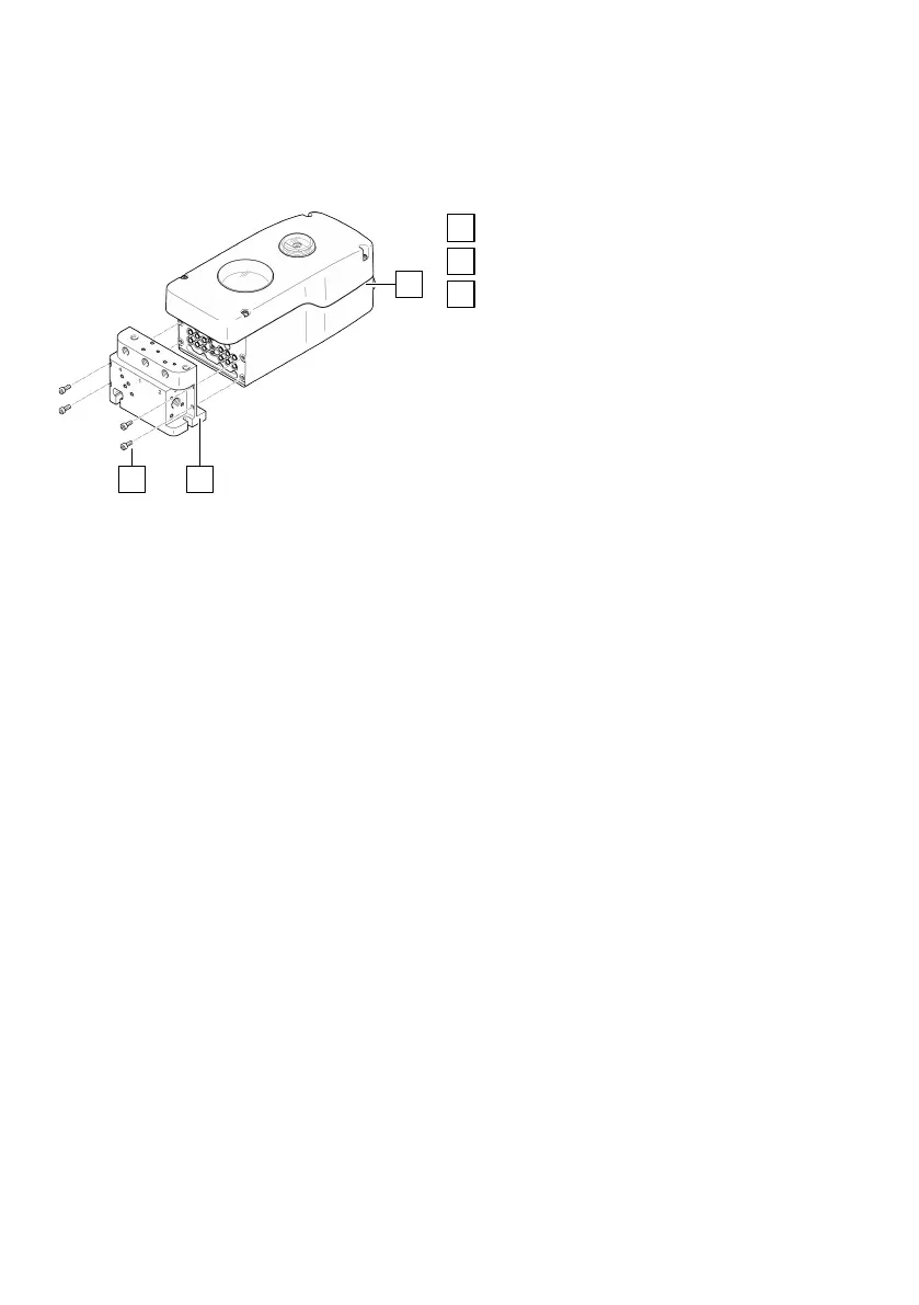
Fig. 9: Mounting of pneumatic manifold block
CAPS
Positioner CMSH-...-V-SD-...
Pneumatic manifold block CAPS
4 retaining screws
Fasten the pneumatic manifold block CAPS to the positioner with 4 retaining screws.
– M4x20 retaining screws for CAPS-M1-VDE1-..., M4x10 retaining screws for CAPS-M1-VDE2-...
–
Tightening torque: 2.7 Nm ± 10%
5.2
Mounting on semi-rotary drives
5.2.1 Mounting the shaft adapter on the CMSH-S-...
The shaft of the internal position sensor can be rotated as desired and does not have a mechanical
stop for the sensing range. The permissible sensing range of the position sensor is 115°.
The sensing range of the position sensor can be checked in Operation mode ‘Manual venting’
è
7.2.3.2 ‘Manual venting’ manual manipulated variable mode.
For the position sensor to work within its sensing range, the mounting position as well as the initial
position and direction of rotation of the drive must be taken into account when determining the shaft
adapter position on the shaft.