1. Installation
1-15
Festo CPX-FB36-EN en 1611a English
1.3.4 Network connections
There are two 4-pin, D-coded M12 sockets on the bus node
for the network connection. The sockets are compatible with
SPEEDCON plugs.
Both connections have “Auto-Negotiation” and “Crossover”
detection (factory setting).
When crossover detection is activated, the bus node automat
ically exchanges the transmitted and received data.
If crossover detection is deactivated, assignment of the pins
for transmitted and received data at the XP2 connection is
crossed. As a result, several bus nodes in a row can each be
connected with a patch cable.
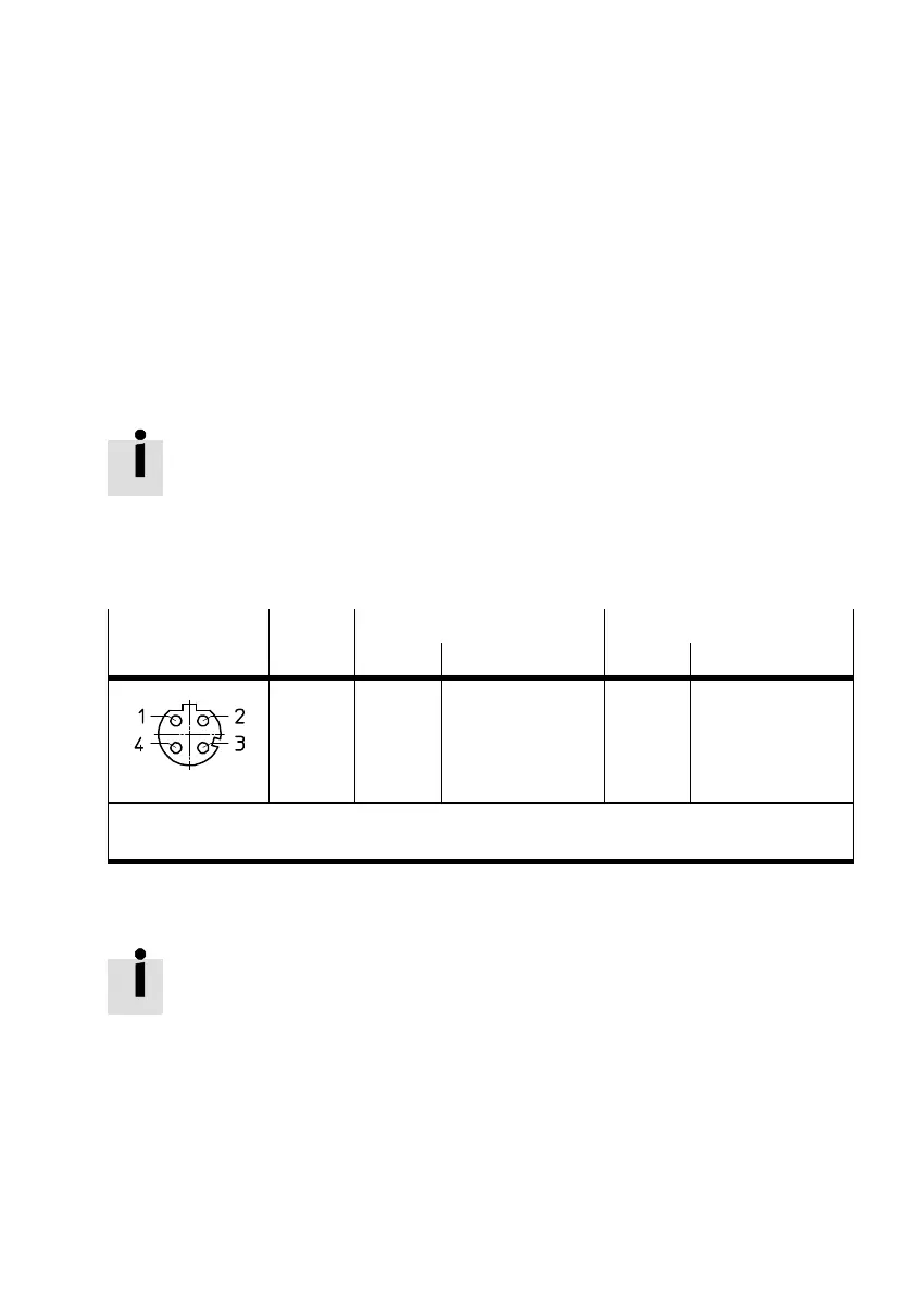
Socket
1)
Pin Connection[X1]
2)
Connection[X2]
2)
M12, 4-pin Signal Explanation Signal Explanation
1
2
3
4
Housing
TD+
RD+
TD–
RD–
Shield
Transmitted data +
Received data +
Transmitted data –
Received data –
Functional earth
RD+
TD+
RD–
TD–
Shield
Received data +
Transmitted data +
Received data –
Transmitted data –
Functional earth
1) Functional earth is accomplished via the housing
2) Pin activation with deactivated crossover detection
Tab. 1/8: Pin allocation of the network connections [X1] and [X2]
If the QuickConnect function has been activated, the crossov
er detection function is not available.
Further notes on wiring with deactivated crossover detection
can be found in chapter 2.1.2.
 Loading...


