Commissioning
10 © Festo Didactic GmbH & Co. • MPS
Execution/Documentation
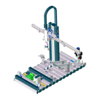
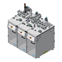
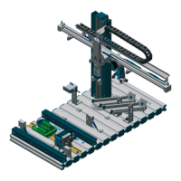
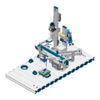
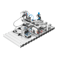
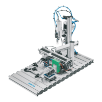
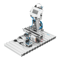
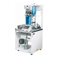
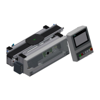
Please complete the list regarding the elements shown and numbered in the
pictures above.
No. Name Ident. Description Page #
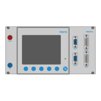
Ex.1 Start-button S1 Push button with light on the Control
Panel, normally open contact,
connected to a PLC-input
no data sheet
Panel: inputs
Ex.2 Proximity
switch,
inductive
2B2 Inductive switch, normally open
contact, activated by a magnet ring in
the piston rod of the flat cylinder with
non-rotating piston rod, send the
information “piston rod of the cylinder
is in up position” to the PLC-input
SME-8-S-LED-24
Station: inputs
Station: pneumatic
PLC-board: inputs
Ex.3 Pneumatic
gripper
3A1 Double acting parallel gripper,
actuated by 2 parallel acting cylinders
inside, with magent ring for end-
position detection, gripper power 27 N
open and close
HGP-10-A
Station: outputs
Station: pneumatic
PLC-board: outputs
No. Name Ident. Description Page #
1 Retro
reflective
sensor
3B1 Retro reflective optical sensor, send out
an infra-red signal and measure the
reflection of the light.
SOEG-L-Q30-PA-S-2L
Station: inputs
PLC-board: inputs
2 Pneumatic flat
cylinder non-
rotating
2A1 Flat cylinder with non-rotating piston
rod, double acting, non-rotating by the
form of the piston rod, with magnet ring
for end-position detection
DGO-12-225-P-A
Station: outputs
Station: pneumatic
PLC-board: outputs
3 Light barrier
sender
IP_N_FO Infrared sender to the previous station,
maximum range 6000 mm
SOEG-S-Q30-S-L
Station: inputs
PLC-board: inputs