Commissioning
© Festo Didactic GmbH & Co. • MPS 11
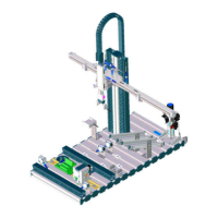
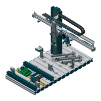
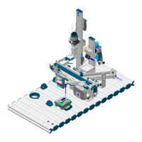
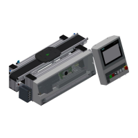
Please analyze the cable connections in your station and complete the drawing on
the next page (Execution and Documentation).
Information
Please fill out all c in the graphic and draw the connections. Use the real station to
check the connections. The standard station don´t have the Emergency Stop board,
which is optional. Therefor all the following projects are defined without this board.
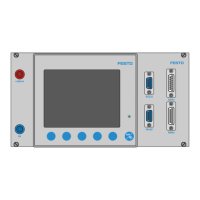
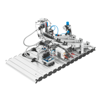
Instructor: Please explain the structure of the PLC to the participants . Which
adress have which module and which module have which function in controlling
the process. Leave the cables all connected to help the participants. Show them
also how to use the technical manual to find out the adress of the module. Please
show the participants which steps and connections are necessary if the stations
are coming with the Emergency Stop board and how to connect the Emergency
switch buttons!!!
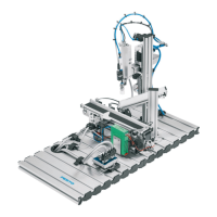
Planning
Please follow the explanations of the instructor first and then plan your activities
step-by-step. Use the real station to find out all connections and identifications. Use
also the technical documentation.
The time to finish this project should be around 0,5 hours.
1.2 Analysis –
Cable connections