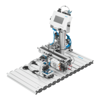
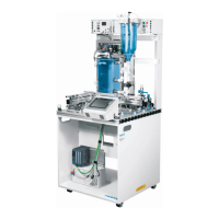
Commissioning
© Festo Didactic GmbH & Co. • MPS 21
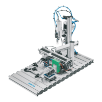
Please check the adjustment of all sensors and of the mechanical components of
your station to prepare the test of the whole process.
Information
To find out the function and location of the sensors, please use the technical
manual. The inputs can also be checked directly at the PLC-LED´s. To move
pneumatic actuators, please switch off the air-pressure and move them manually by
hand. Please be very careful, move the actuators back before switching on the air-
pressure again. Some pneumatic and the electrical actuators can not be moved in
this way-the pneumatic components can be activated by the manual detection
button on the valve (see picture)
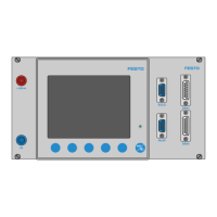
Instructor:show the participants how to find out an input and an output using the
wiring diagrams. Show them why some actuators can not be moved by hand even
without air- and power supply (DC-motors and 5/3-way valves) using the
pneumatic plan to explain. Show them an example how to adjust a sensor to
define the back or front position of a cylinder. Provide the necessary tools.
Deadjust the following sensors and mechanical components (bold)
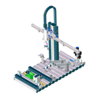
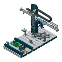
I/O Station
Adress Symbol Ident. Description
I0.0 Part_av Part_AV
Workpiece is available
I0.1 Han_prev 1B1 Handling at previous station
I0.2 Han_foll 1B2 Handling at following station
I0.3 Han_sort 1B3 Handling at sorting position
I0.4 Lift_dow 2B1 Lifting cylinder with gripper is down
I0.5 Lift _up 2B2 Lifting cylinder with gripper is up
I0.6 Sen_mat 3B1 Material detection signal = 0 = black
I0.7 Follow IP_FL Light barrier to the following station
Q0.0 Handprev 1Y1 Solenoid of handling cyl.to previous station
Q0.1 Handfoll 1Y2 Solenoid of handling cyl.to following station
Q0.2 Lifting 2Y1 Solenoid of the lifting cylinder with gripper
Q0.3 Gripper 3Y1 Solenoid of the gripper = 1 = open
Q0.7 Previous IP_N_FO
Light barrier to the previous station
Deadjust the workpiece mounting so that the gripper is not able to pick up the
workpiece centred and close the one-way-flow control valve of the lifting cylinder
to move up.
1.5 Commissioning –
Adjustment of the
Station