© Festo Didactic GmbH & Co. • MPS 9
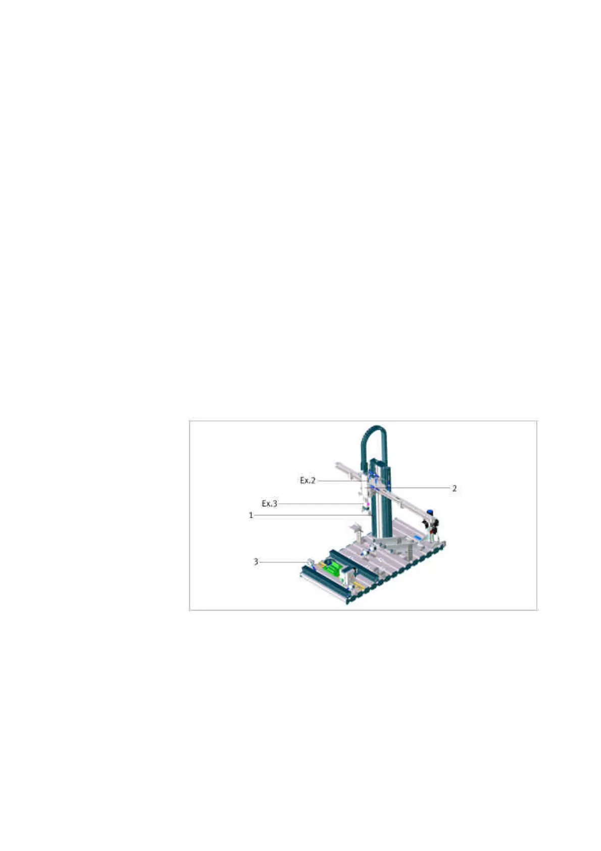
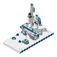
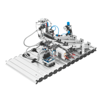
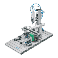
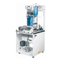
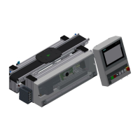
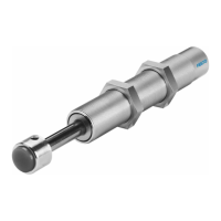
Please list up all the “sensors” and “actuators” shown in the picture below (1 – 3).
Name the elements with identification in the wiring diagram/pneumatic plan and
describe shortly their function generally (not the function within the system).
Information
Please use the technical manual-data sheets, pneumatic plan and wiring diagrams.
Please refer to the examples (Ex.1 – Ex.3) mentioned below in the table of the
execution work-sheet. Please follow the numbers (1 – 3) shown in the pictures below
(Ex.1 is not shown in the graphics).
Instructor: Show one example to the participants how to find an in- and output in
the wiring diagrams and how to find the data sheet using the order number printed
on the element itself. Show the participants at the station itself which components
they have to identify. There are 4 different wiring diagrams for each station: the
station itself (Station), the Control Panel (Panel), the PLC-board (PLC-board) and
the Emergency-Stop (if available – optional). Please use one of the Examples -
Ex.2 or Ex. 3.
Planning
Please plan your project within the whole team carefully. Use the technical manual
and the real station to do this project. Please describe the function of the element in
general, not within the signal- and materialflow of the station. To find the data-sheet
of the elements, please see the list of components first and check the order no.
printed on the element itself.
The time to finish this project should be around 1,5 hours.
1.1 Analysis –
Components
identification
Commissioning