3.1.4.2 Pneumatic
Ports for compressed air supply (1) and common exhaust (3) are available both on the controller and
on the right-hand end of the manifold rail. The ports are internally connected in each case and can be
used alternately or in parallel.
Ports (1) and (3) on the manifold rail should be selected for flow-intensive applications. For further
improvement an independent, parallel circuitry for both the supply and exhaust ports should be
selected. More information can be found in the support portal
è
www.festo.com/sp.
The product can be operated with internal or external pilot air.
– The pressure at port (1) must be > 3 bar for the internal pilot air supply.
–
The pressure at port (14) must be > 3 bar for the external pilot air supply.
Pressure at port (1) is monitored by the device. If the pressure is less than 3 bar at port (1), an
external pilot air supply of at least 3 bar is required; the negative pressure monitoring at (1) must
be deactivated via the corresponding CPX module parameter
è
Tab. 3 Overview of the CPX module
parameters. The device does not monitor the pressure for port (14).
With external pilot air supply, it must always be maintained for the entire duration of operation. After a
pressure loss, a voltage reset is required before operation can be continued without error.
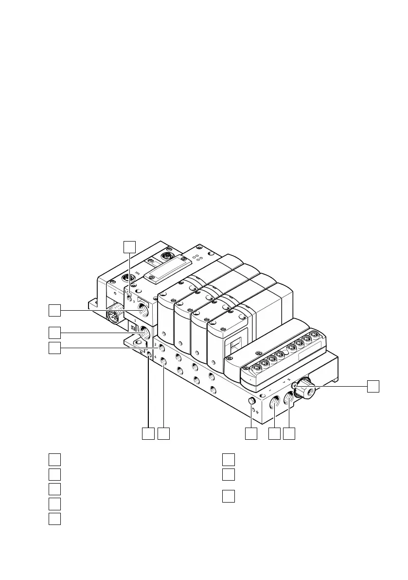
Fig. 15: Pneumatic ports
M7 port for pressure compensation (L)
G3/8 port for common exhaust/vacuum (3)
G3/8 port for compressed air supply (1)
Ports G1/8 for working air (2)
M7 port for pilot exhaust air (84)
Ports G1/8 for working air (4)
Selector for external pilot air or blanking
plugs for internal pilot air M5
M5 port for external pilot air (14) or
blanking plugs for internal pilot air