Valve on slots 0 … 7
Byte 5 Byte 4 Byte 3 Byte 2 Byte 1 Byte 0
Value Parameter Command
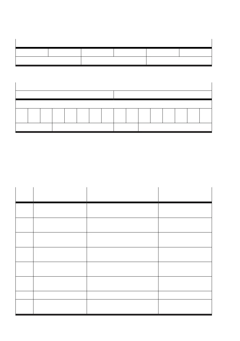
Tab. 52: Structure of the output data (PDO) per valve
The following table is a detailed view of the "Command" section.
Detailed view of the "Command" section
PDO byte 1 PDO byte 0
Status
Bit
7
Bit
6
Bit
5
Bit
4
Bit
3
Bit
2
Bit
1
Bit
0
Bit
7
Bit
6
Bit
5
Bit
4
Bit
3
Bit
2
Bit
1
Bit
0
transfer control channel – valve mode = 63
Tab. 53: Detailed view of the "Command" section of the output data (PDO)
Byte 0
The valve is set to transfer mode with the value "63" using the valve operating mode (valve mode,
PDO byte 0, bits 5 … 0).
Bits 7 … 6 in byte 0 (PDO) are ignored in transfer mode.
Channel (channel)
The channel over which the information is to be transferred is selected with bits 4 … 0 in byte 1 (PDO).
Values that are not listed are reserved and cannot be used.
Value
dec.
1)
Channel Meaning Access
1 parameter set 1 Parameterisation in parameter set
1
read/write
2 parameter set 2 Parameterisation in parameter set
2
read/write
3 parameter set 3 Parameterisation in parameter set
3
read/write
4 parameter set 4 Parameterisation in parameter set
4
read/write
5 parameter set 5 Parameterisation in parameter set
5
read/write
14 terminal settings Settings of the entire Motion Ter-
minal
read/write
15 valve settings Valve settings read/write
16 input module settings Parameterisation of the input mod-
ules
read/write