Valve on slots 0 … 7
Byte 5 Byte 4 Byte 3 Byte 2 Byte 1 Byte 0
Value Parameter Status
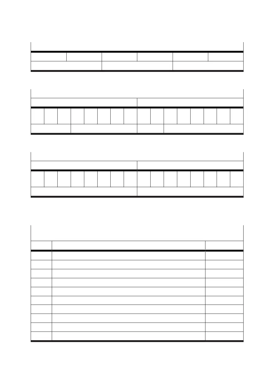
Tab. 60: Structure of the input data (PDI)
The following table is a detailed view of the "Status" section.
Detailed view of the "Status" section
PDI byte 1 PDI byte 0
Bit
7
Bit
6
Bit
5
Bit
4
Bit
3
Bit
2
Bit
1
Bit
0
Bit
7
Bit
6
Bit
5
Bit
4
Bit
3
Bit
2
Bit
1
Bit
0
transfer control channel valve state valve mode = 63
Tab. 61: Detailed view of the "Status" section of the input data (PDI)
The following table is a detailed view of the "Parameters" section.
Detailed view of the "Parameters" section
PDI byte 3 PDI byte 2
Bit
7
Bit
6
Bit
5
Bit
4
Bit
3
Bit
2
Bit
1
Bit
0
Bit
7
Bit
6
Bit
5
Bit
4
Bit
3
Bit
2
Bit
1
Bit
0
index addressed target
Tab. 62: Detailed view of the "Parameters" section of the input data (PDI)
3.5.4.2 Information on the status of the Motion Terminal (info channel)
Channel 25 enables the read-out of various information that shows the status of the Motion Terminal.
Hardware information
Channel 25, addressed target 1
Index Meaning Value digit
1 Hardware ID of the controller CTMM-S1-C 1
2 Hardware ID of the interlinking board 1
21 Hardware revision valve 0 1
41 Hardware revision valve 1 1
61 Hardware revision valve 2 1
81 Hardware revision valve 3 1
101 Hardware revision valve 4 1
121 Hardware revision valve 5 1
141 Hardware revision valve 6 1
161 Hardware revision valve 7 1