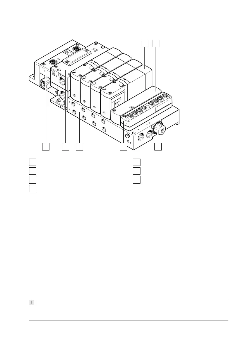
Fig. 6: Product design
CPX terminal electronics side
Controller Motion Terminal CTMM-S1-C
Manifold rail
Input module CTMM-S1-A/D-… (optional)
Pilot pressure regulator
Cover plate VABB-P11-27-T (optional)
Valve slice VEVM-S1-27-…
3.1.1.1
CPX terminal electronics side
The CPX terminal establishes the connection to a higher-order controller (
è
6.1 Supported CPX bus
nodes) by means of an internal controller (CPX-CEC-...-V3) or a bus node.
3.1.1.2 Controller Motion Terminal CTMM-S1-C
The Motion Terminal controller forms the interface between the CPX terminal and the components of
the Motion Terminal.
The controller has an Ethernet interface for accessing the WebConfig user interface for the Motion
Terminal. Compressed air (1) and common exhaust or vacuum (3), as well as pilot exhaust air (84) and
pressure compensation (L) can be connected to the controller housing.
From the perspective of the CPX terminal, the Motion Terminal is a single component and is modelled
with a defined amount of input and output data in the process data of the CPX terminal
è
3.5
Communication between PLC and Motion Terminal.
The terminal CPX and the CPX module CTMM-S1-C can be parameterised with the operator unit
(CPX-MMI), the Festo Maintenance Tool (CPX-FMT) software or the higher-level system.
Further information on the parameterisation of the CPX system and its modules can be found in the
CPX terminal manual
è
1.1 Applicable documents.