1. Summary of components
1−19
Festo P.BE−VTSA−44−EN en 0509NH
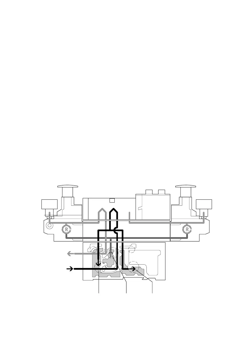
Reversible AB pressure
regulator (identifier
R5−...−6 and R5−...−10)
Mode of operation:
With the reversible pressure regulator the supply air (chan
nel 1) is divided and passed directly to both pressure regu
lators. In each case the regulated air is present in channels 3
and 5 on the valve. The valve is therefore operated revers
ibly
(see fig.). This means:
channel 3 passes the working pressure to connection 2
channel 5 passes the working pressure to connection 4.
The following example shows the following switching
position:
The supply air in channel 1 is passed in the pressure
regulating plate to pressure regulators A and B, regulated
there and then passed
to connections 3 and 5 on the valve.
In the valve the supply air is passed to connection 2 on the
manifold block. The exhaust is passed via channel 4 in the
pressure regulator plate and split there to channels 3 and 5
and exhausted.
123
Connection 2 (B)
Connection 4 (A)
1 Channel 5 (exhaust)
2 Channel 1 (supply air)
3 Channel 3 (exhaust)