1. Summary of components
1−21
Festo P.BE−VTSA−44−EN en 0509NH
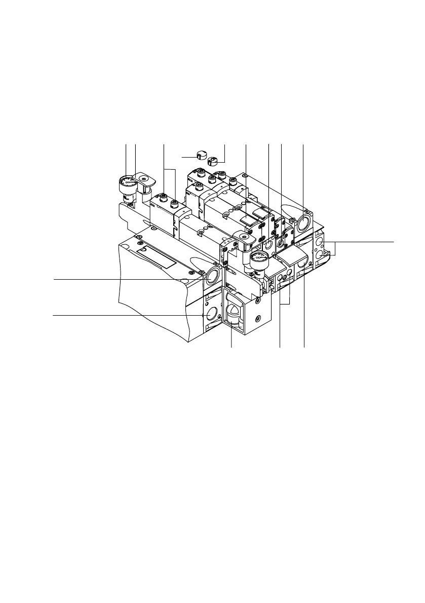
You will find the following pneumatic connecting and operat
ing elements on the VTSA valve terminal:
8 9
aJ
aB
aA
aB
712 34
5
6
aA
9
1
Manometer (optional)
2 Adjusting knob of the optional
pressure regulator plate
3 Manual override (per pilot solenoid,
non−locking or turning/locking)
4 Optional manual override cap
(manual override without function)
5 Optional manual override cap, for
non−locking function of manual
override
6 Identification fields
7 Adjusting screw of the optional
throttle plate
8 Supply connection (1) of the optional
vertical supply plate
9 Exhaust connections Valves" (3/5)
aJ Pilot connections (12) and (14) for
supplying the external pilot air
aA Supply connection (1) Operating
pressure"
aB Work connections (2) and (4), for
each valve location
Fig.1/7: Pneumatic connecting, display and operating elements of the VTSA valve
terminal