2. Fitting
2−12
Festo P.BE−VTSA−44−EN en 0509NH
Variant Fastening possibility
1
2
1
2
3
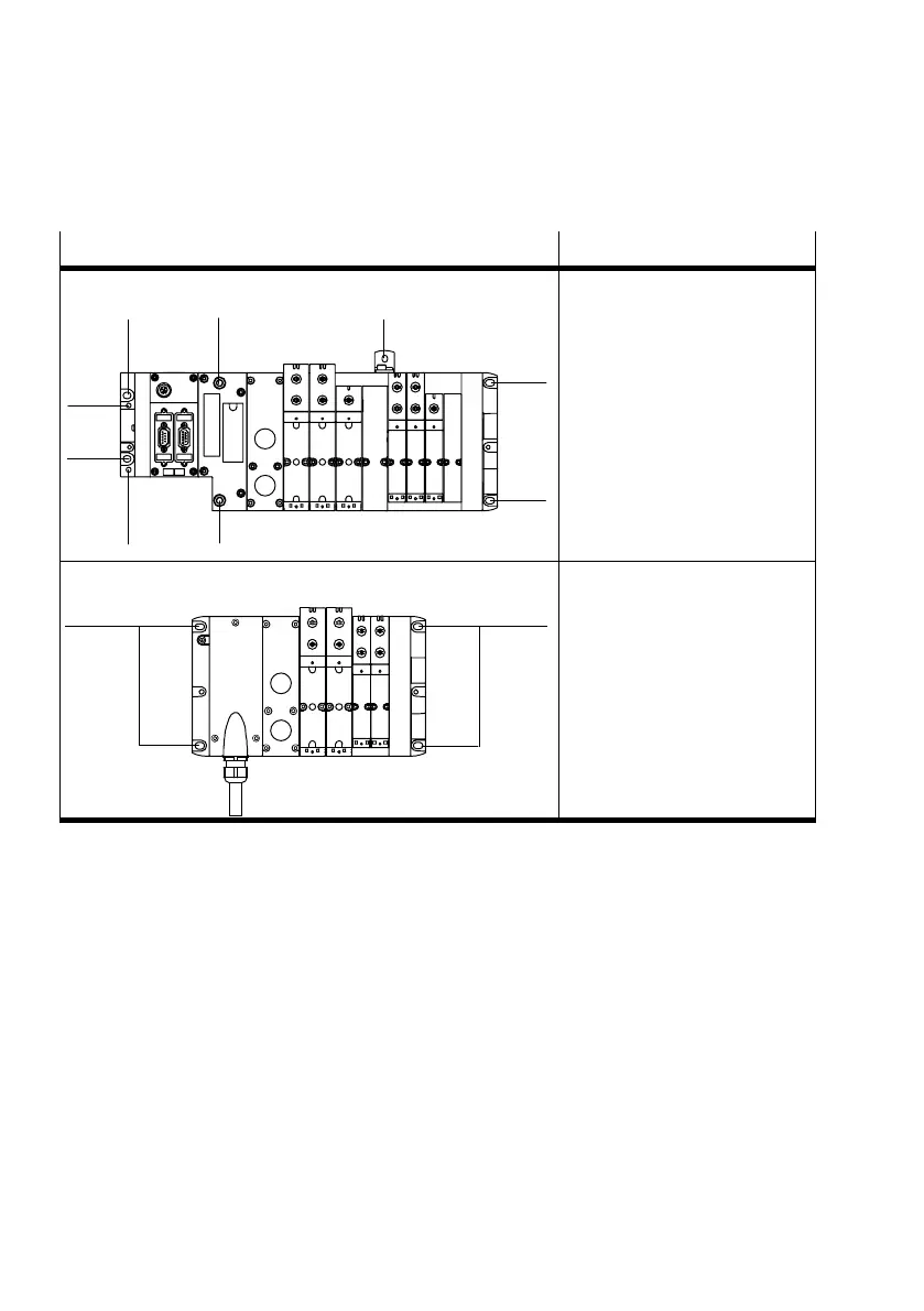
VTSA valve terminal with CPX terminal
1
1
1
1
End plates: 2 M6 screws each
(left−hand end plate alter
natiely 2 M4 screws)
Pneumatic interface (CPX):
two M6 screws, hexagon
socket
Optional bracket on the
pneumatic supply plate:
one M5 screw
1 Hole for M6 screw
2 Holes for M4 screws
3 Holes for M5 screws in the
bracket
11
VTSA valve terminal with multipin node
Multi−pin node:
two M6 screws
Right−hand end plate:
two M6 screws
1 Hole for M6 screw
Tab.2/3: Possibilities of fitting the VTSA valve terminal onto a wall
Dismantling Proceed as follows:
1. Prevent a hanging valve terminal from falling down before
you loosen it from the fastening surface.
2. Loosen the fastening screws (see Tab.2/3).
3. Remove the valve terminal from the fastening surface.