3. Installation
3−14
Festo P.BE−VTSA−44−EN en 0509NH
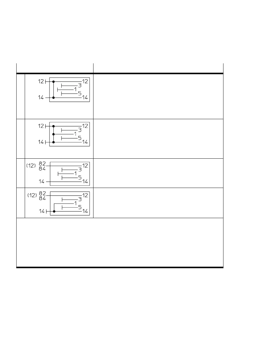
Settings of the code cover Description
1)
1 Setting of the code cover for pilot control with external pilot
air:
Pilot air is supplied via connection 14.
Connection 12 must be closed as connections 12 and 14 are
connected internally.
The pilot air is exhausted non−ducted at the valves via the
valve housing.
2 Setting of the code cover for pilot control with internal pilot
air:
Pilot air branched from channel 1.
Connections 12 and 14 sealed.
The pilot air is exhausted non−ducted at the valves via the
valve housing.
3 Setting of the code cover for pilot control with external pilot
air, ducted pilot exhaust and breathable exhaust air:
2)
Pilot air via connection 14.
Pilot air (82/84) and breathable exhaust via connection 12.
4 Setting of the code cover for pilot control with internal pilot
air, ducted pilot exhaust and breathable exhaust air:
2)
Pilot air branched from channel 1.
Pilot air (82/84) and breathable exhaust via connection 12.
1)
Reversible 2x3/2−way valves from Festo (identifier T32N−A, T32F−A, T32W−A) require for the
pneumatic spring function supply pressure at connection 12.
2)
Please note:
Settings 3 and 4 of the code cover enable the ducted exhaust of the pilot and breathable exhaust
air, when the valve terminal is not fitted with reversible 2x3/2−way valves from Festo. The seals
between the manifold plates and the valves must be fitted here in the relevant position (see
chapter 5.4.1). Note that the ducted exhaust of the pilot and breathable air via connection 12
does not correspond to standard ISO 15407−2.
Tab.3/2: Settings of the code cover of the selector end plate type VABE−...RZ−...B1