Reproduction forbidden without Fibocom Wireless Inc. written authorization - All Rights Reserved.
FIBOCOM SU806 Series Hardware Guide Page 60 of 91
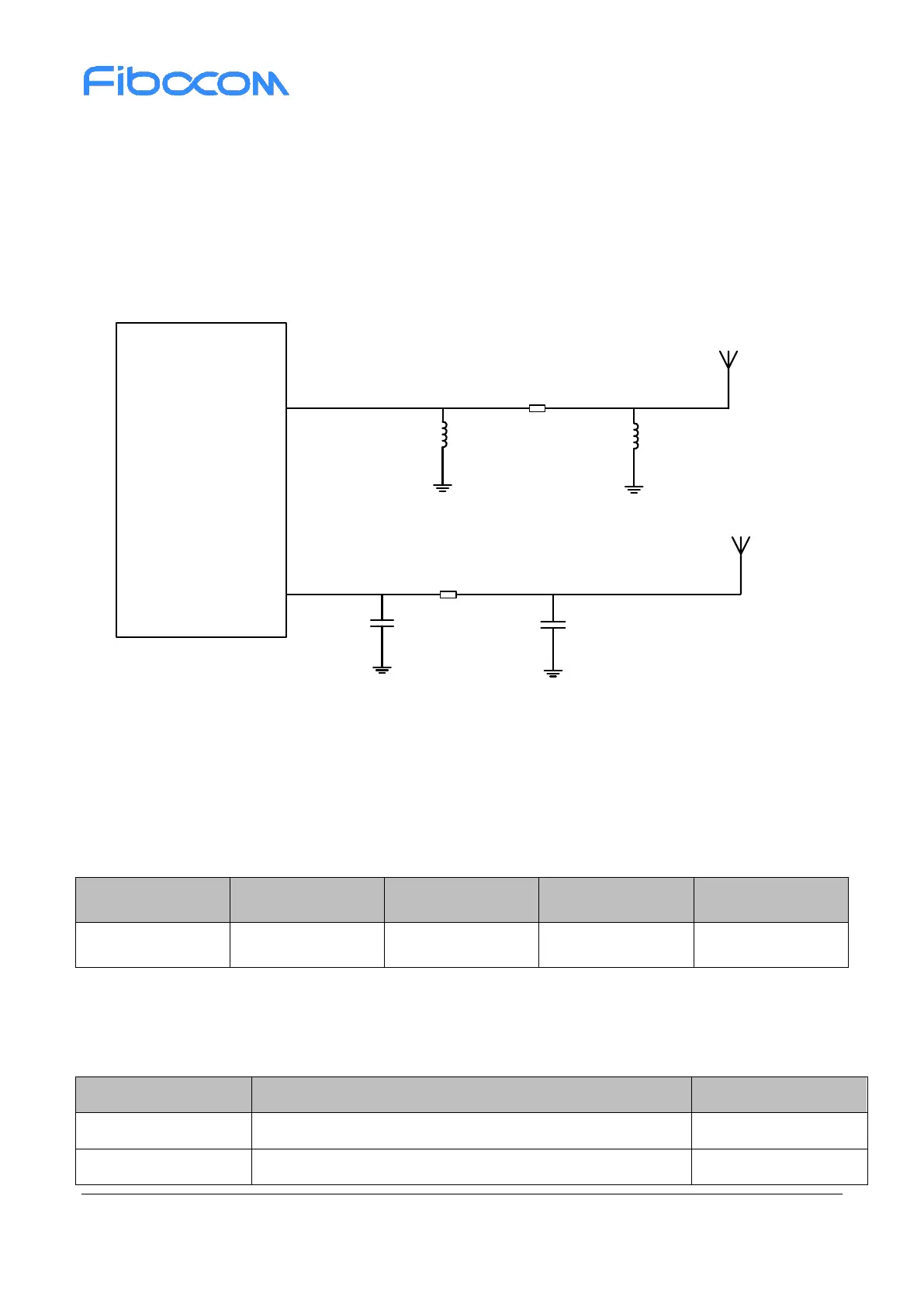
4.1.2 Antenna Reference Design
When use the SU806 series module, it is necessary to connect the antenna pin with the RF connector or
antenna feed point on the main board via an RF trace. Microstrip trace is recommended for RF trace, with
insertion loss within 0.2dB and impedance at 50Ω.A π-type circuit is reserved between the module and
the antenna connector (or feed point) for antenna debugging. Two parallel components are directly
connected across the RF trace and should not pull out a branch, as the figure shows:
Module
ANT_MAIN
ANT_DRX
0R
NC
NC
Main_Antenna
Diversity_Antenna
NC
0R
NC
Figure 4-1 MAIN/DRX antenna reference design
4.2 WIFI/BT Antenna
Microstrip trace is recommended for the WIFI/BT RF route, with insertion loss within 0.2dB and
impedance at 50Ω.
Table 4-4 WIFI/BT antenna interface definition
4.2.1 WIFI/BT Operating Frequency
Table 4-5 WIFI/BT operating frequency

 Loading...