Reproduction forbidden without Fibocom Wireless Inc. written authorization - All Rights Reserved.
FIBOCOM SU806 Series Hardware Guide Page 44 of 91
3.13 Charge Enable Interface
Table 3-17 Charge enable interface pin definition
The module does not support
charging, and DC-DC circuit can be
added if charging function is required.
3.14 Vibration Motor Driver Interface
Table 3-18 Vibration motor driver pin definition
Vibration motor driver output
Can be configured as LDO mode and
connect with Vibration motor +
3.15 LCM
The video output of SU806 series module can support single-screen display. Its screen interface is based
on MIPI_DSI standard and supports 4 sets of high-speed differential data transmit, and supports HD+
maximum.
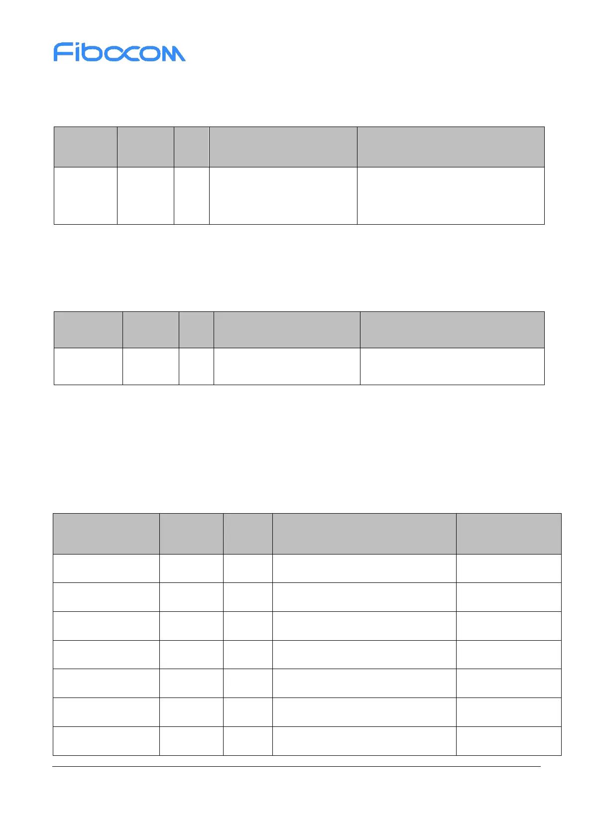
Table 3-19 LCM pin definition
MIPI display serial interface clock -
MIPI display serial interface clock +
MIPI display serial interface Lane0 -
MIPI display serial interface Lane0 +
MIPI display serial interface Lane 1-

 Loading...