EasyManuals Logo

Fibocom SU806 Series User Manual

Fibocom SU806 Series
91 pages
To Next Page IconTo Next Page
To Previous Page IconTo Previous Page
Page #47 background imageLoading...
Page #47 background image
Reproduction forbidden without Fibocom Wireless Inc. written authorization - All Rights Reserved.
FIBOCOM SU806 Series Hardware Guide Page 47 of 91
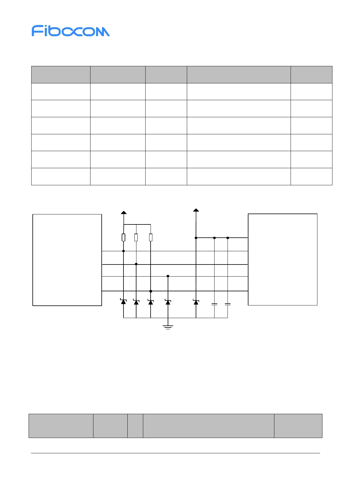
power, interrupt, reset pins. The pin definition of the module is shown in the follow table:
Table 3-21 TP pin definition
Pin Name
Pin Number
I/O
Description
Note
TP_INT
30
DI
LCD TP interrupt signal
-
TP_RST
31
DO
LCD TP reset signal
-
VDD1V85
111
PO
LCD TP IO voltage output
-
VDD2V8
228
PO
LCD TP VDD voltage output
-
TP_I2C_SCL
47
DO
LCD TP I2C clock
-
TP_I2C_SDA
48
I/O
LCD TP I2C data
-
TP reference design circuit is shown as follows:
TS_I2C_SCL
TS_I2C_SDA
TP_RST
TP_INT
SCL
SDA
VDD1V85
RESET
INT
VDD
NC
10K
NC
VDD2V8
100nF2.2uF
TP
Module
Figure 3-16 TP reference design
3.17 Camera
The camera interface is based on the MIPI_CSI standard and can support three (4-lane+2-lane+1-lane)
cameras, maximum 13MP. The pin definition of camera interface is shown in the following table:
Table 3-22 Camera interface pin definition
Pin Name
Pin
Number
I/O
4-Lane+2-Lane+1-Lane
Note

Table of Contents

Questions and Answers:

Question and Answer IconNeed help?

Do you have a question about the Fibocom SU806 Series and is the answer not in the manual?

Fibocom SU806 Series Specifications

General IconGeneral
BrandFibocom
ModelSU806 Series
CategoryComputer Hardware
LanguageEnglish

Related product manuals