COMPONENTS 33
TO INSTALL THE MOTHERBOARD IN THE CHASSIS
When you handle electronic components, you must follow standard electrostatic (ESD)
precautions. For more information, see “Standard electrostatic discharge precautions” on
page 11.
1. Lower the motherboard into the chassis at a 45-degree angle and carefully insert the
connector panel connectors through the connector panel cutouts. Lay the motherboard flat
and align the motherboard with the screw holes in the bottom of the chassis.
As you install it, be careful to avoid stressing the motherboard or the surrounding cables in
the chassis. Make sure to position the metal fingers on the USB connectors.
2. Install the motherboard screws into the chassis (five screws).
3. Connect the following cables from the motherboard (see Figure 9 on page 24):
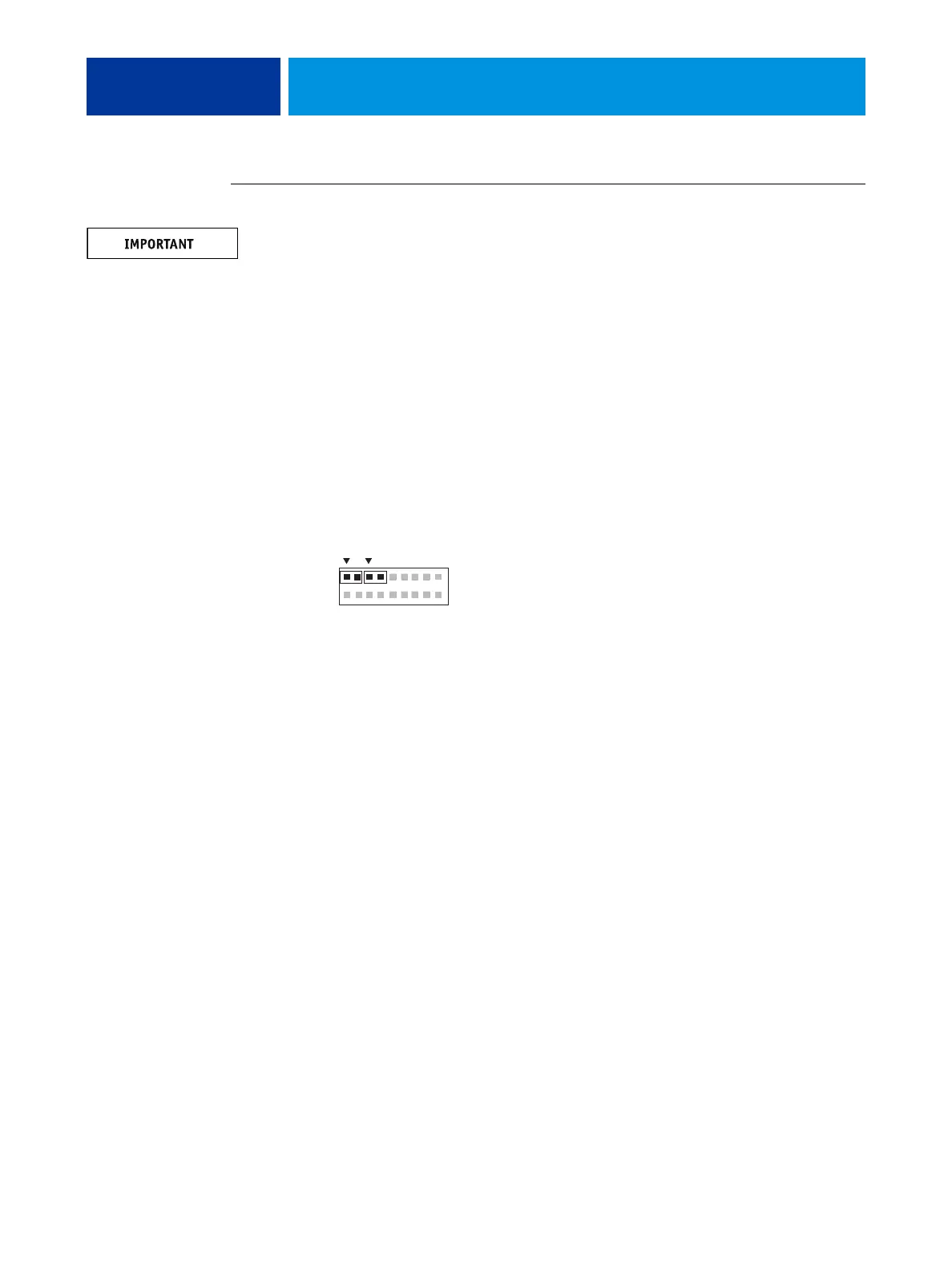
• Power button cables (two) at motherboard connector labeled J14
Four wires left to right: red, black, red, yellow
The two 2-wire cables are labeled SW LED and SW. SW LED wires are red and black;
SW wires are red and yellow.
• Enclosed fan cable to FAN2
• HDD cable to SATA1
• Power supply cables: 20-pin cable for MB power; 4-pin cable for CPU power
4. Install the copier interface board (see page 36).
5. Reassemble the E100 (see page 18) and start the E100.
6. Configure the date and time in Setup (for details, see the Configuration and Setup, which is
part of the user documentation set).
7. Print a Configuration page to verify system settings and features (see page 19).
1
2
17
18
SWSW LED