COMPONENTS 37
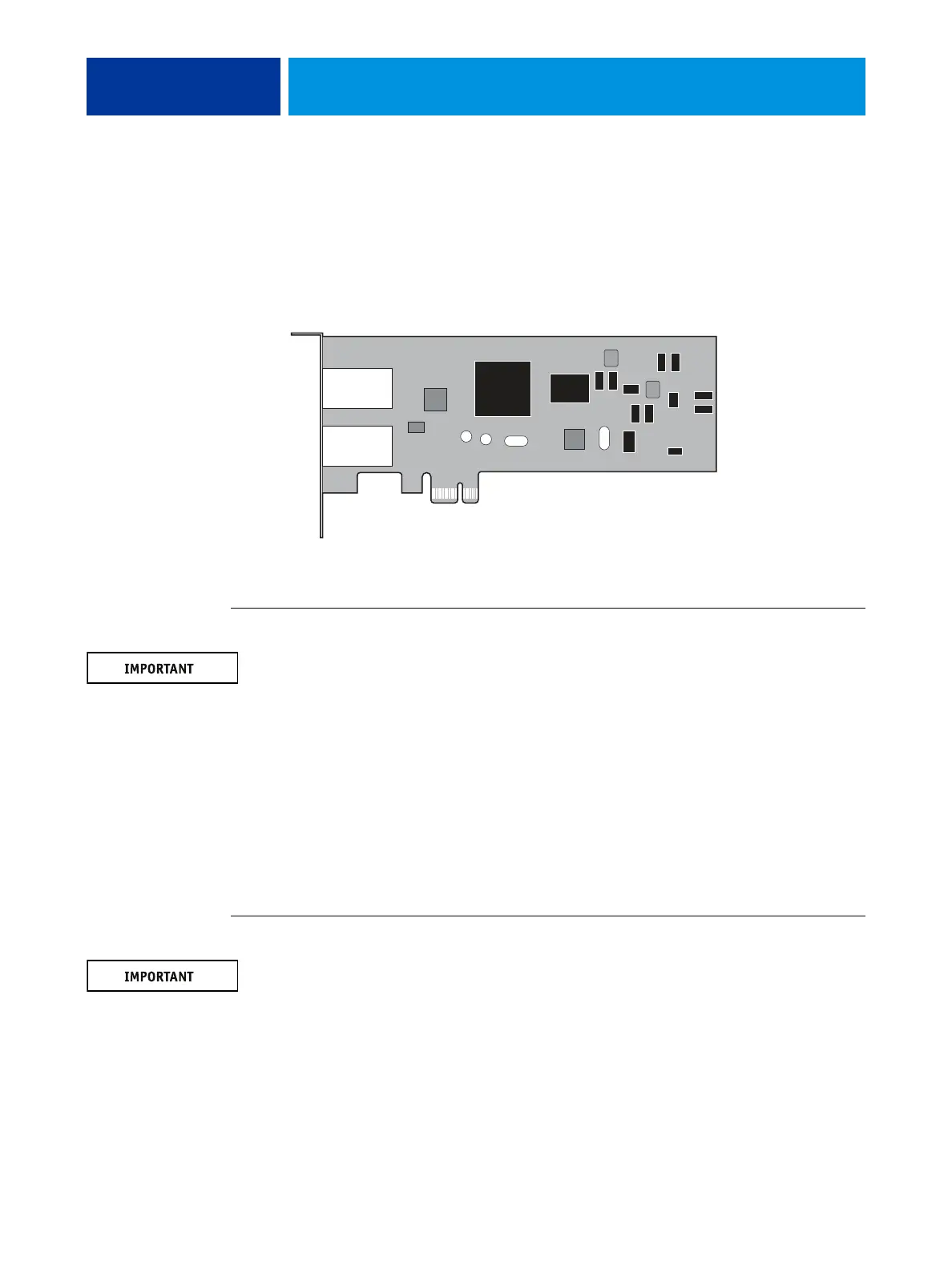
Network switch board
The E100 connects to the copier by means of a network switch board. With this board, you
can create separate IP addresses for the E100 and the copier, which is a required step when
enabling some functions on the E100.
The network switch board connects to the small PCI connector on the motherboard.
FIGURE 15: Network switch board
TO REMOVE THE NETWORK SWITCH BOARD
You must follow standard electrostatic discharge (ESD) precautions when you handle
electronic components. For more information, see “Standard electrostatic discharge
precautions” on page 11.
1. Shut down and open the E100 (see page 14).
2. Remove the mounting screws that connect the network switch board to the bracket on the
connector panel.
Do not remove the two jackscrews that connect the bracket to the network switch board. Save
the screws for later.
3. Lift the network switch board from the chassis.
4. Place the network switch board on an antistatic surface.
TO REPLACE THE NETWORK SWITCH BOARD
When you handle electronics components, you must follow standard electrostatic discharge
(ESD) precautions. For more information, see “Standard electrostatic discharge precautions”
on page 11.
1. Connect the network switch board to the small PCI connector on the motherboard.
2. Secure the network switch board to the bracket on the connector panel with the two
mounting screws that you removed earlier.
3. Reassemble the unit and verify functionality (see page 18).