COMPONENTS 44
5. Lower the socket lever and place it in the locked position under the retention post.
6. Prepare the CPU cooling assembly for installation.
• Make sure that the motherboard is placed on a padded, static-free work surface.
• Apply fresh thermal compound, as described in step 1 on page 43.
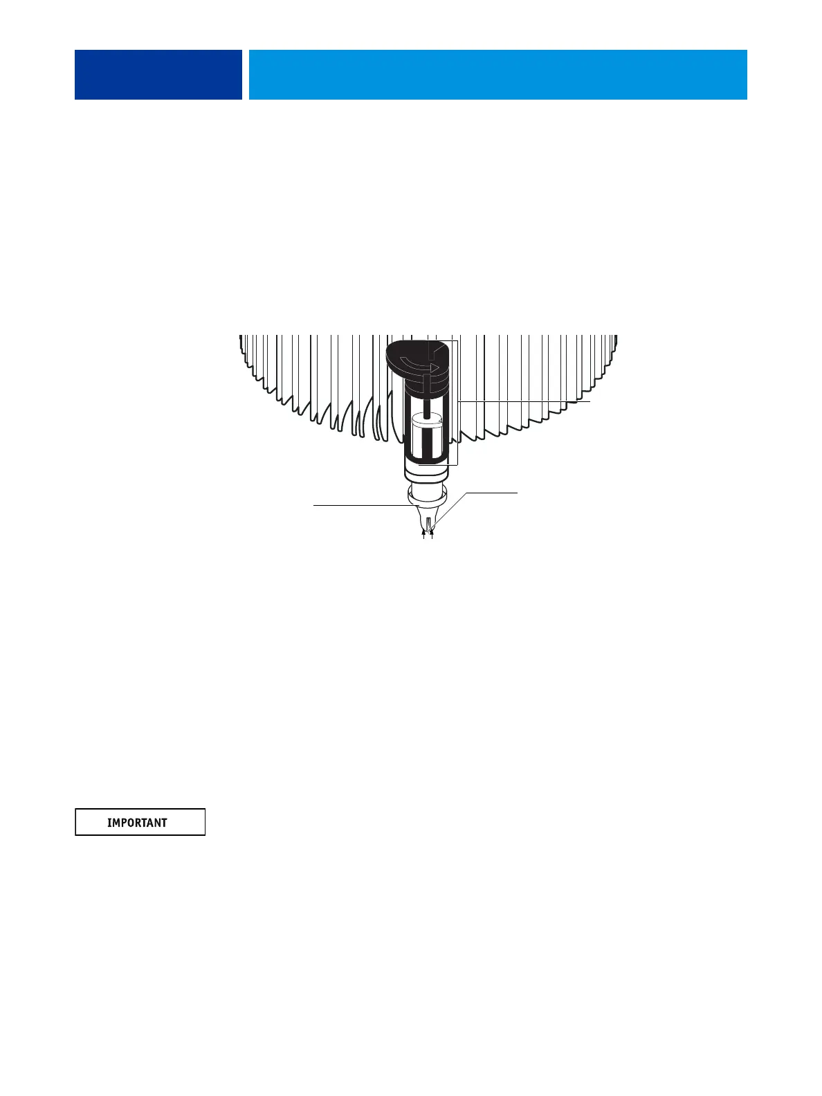
• Rotate fasteners to the position shown below by turning them clockwise (that is, in the
opposite direction of the arrow on top of the fastener).
• Ensure that the pin inside each peg is fully retracted upward.
FIGURE 21: Replacing the CPU cooling assembly
7. Place the heatsink over the CPU socket.
• Align the cooling assembly so that when it is installed, the fan cable easily reaches
connector CPUFAN on the motherboard.
• Align the pegs over their mounting holes in the motherboard.
NOTE: Make sure that each fastener is rotated to the position shown in Figure 21.
8. At opposite corners, press down on each fastener until the retaining tang at the tip of the
peg clicks into locked position and the fastener cannot be pressed down further. Engage all
four pegs.
NOTE: Do not rotate the fasteners after installation.
Engaging the pegs at opposite corners applies clamping force equally over the CPU and
socket. Avoid using excessive force and take care not to flex the motherboard when you
engage the pegs.
Before placing the cooling
assembly on the socket,
rotate each fastener to
this position.
Peg
Ensure that each pin is
fully retracted upward
inside its peg.