COMPONENTS 36
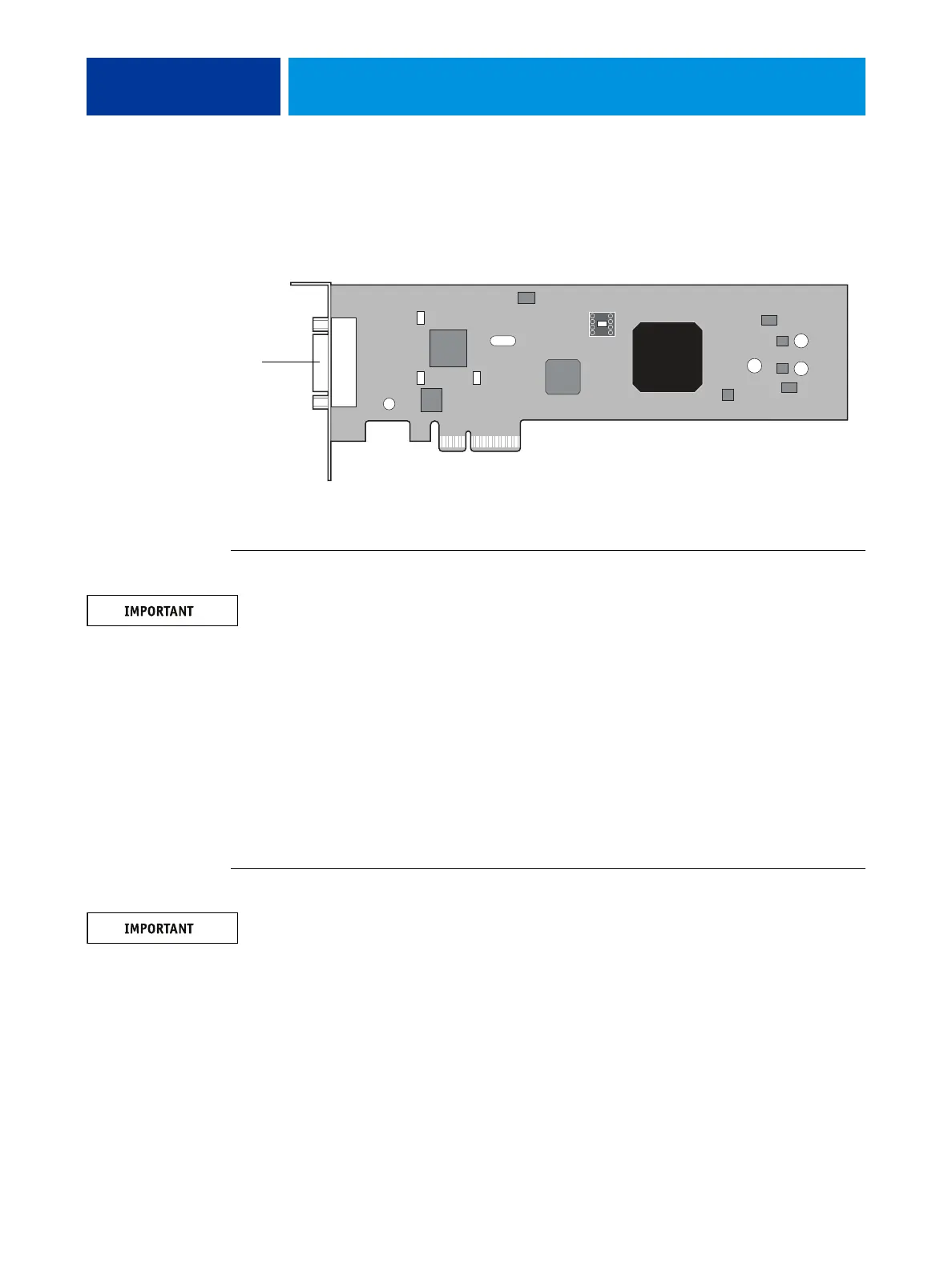
Copier interface board
The copier interface board connects to the large PCI connector (PCIEXP1) on the
motherboard.
FIGURE 14: Copier interface board
TO REMOVE THE COPIER INTERFACE BOARD
You must follow standard electrostatic discharge (ESD) precautions when you handle
electronic components. For more information, see “Standard electrostatic discharge
precautions” on page 11.
1. Shut down and open the E100 (see page 14).
2. Remove the mounting screws that connect the copier interface board bracket to the
connector panel.
Do not remove the two jackscrews that connect the bracket to the copier interface board.
3. Lift the copier interface board from the chassis.
Set the board and the screws aside.
4. Place the copier interface board on an antistatic surface.
TO REPLACE THE COPIER INTERFACE BOARD
You must follow standard electrostatic discharge (ESD) precautions when you handle
electronic components. For more information, see “Standard electrostatic discharge
precautions” on page 11.
1. Connect the copier interface board to the large PCI connector (PCIEXP1) on the motherboard.
2. Secure the copier interface board bracket to the connector panel with the two mounting
screws that you removed earlier.
3. Reassemble the unit and verify functionality (see page 18).
4. Shut down and open the E100 (see page 14).
Copier interface port