2.0 SYSTEM OVERVIEW
2-4 Cheetah Xi 50 Installation Manual UL S2203
Rev 6, 09/2015 P/N: 06-369 FM
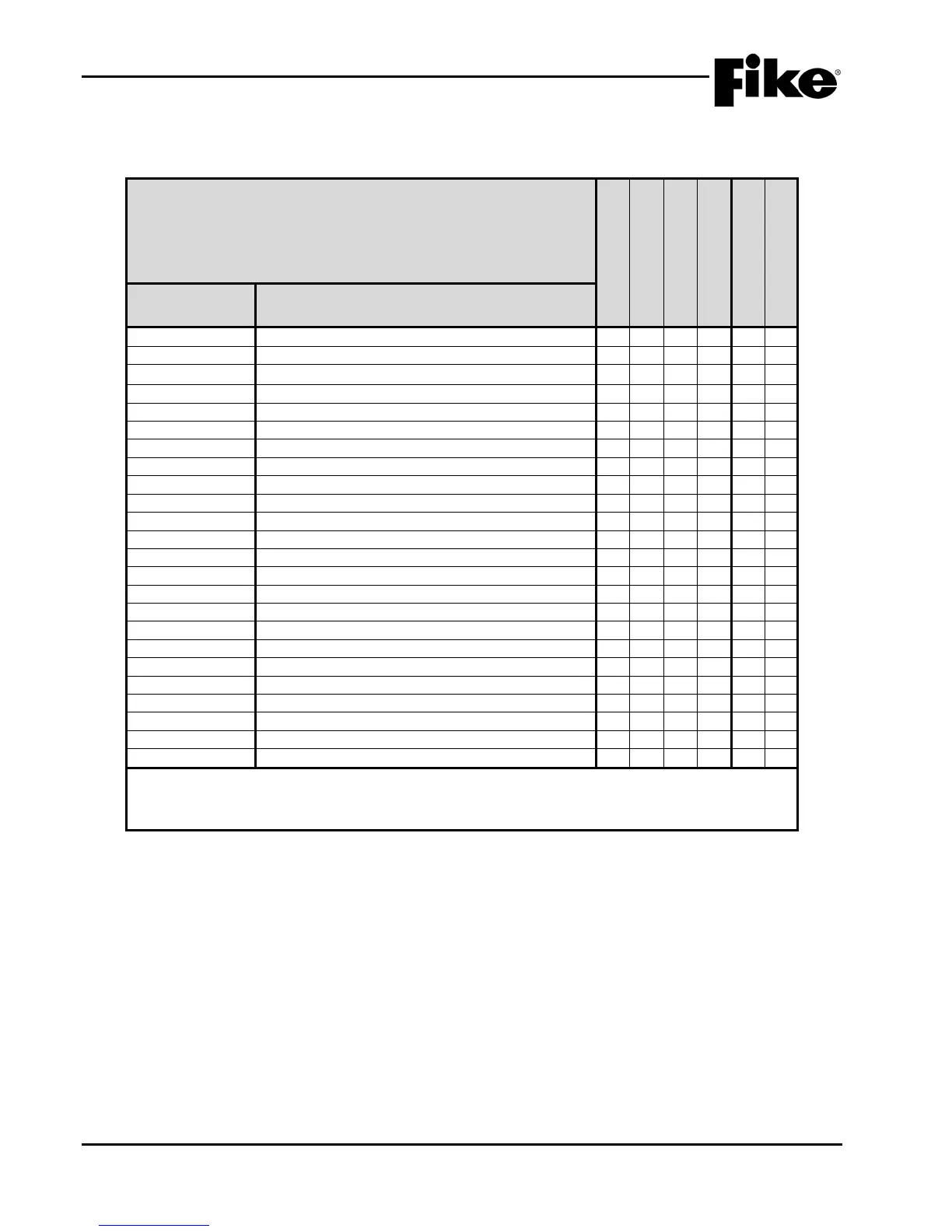
2.1.4 MINIMUM SYSTEM CONFIGURATIONS
Exhibit 2-2: MINIMUM SYSTEM CONFIGURATIONS
This table indicates the minimum components needed to meet the intended
applications.
Y = Yes
N = No
O = Optional
Protected Premises
(Local)
Central Station (PPU)
Remote Supervising
Releasing Service
UL Listed
FM Approved
10-2623 Cheetah Xi 50 Enclosures Y Y Y Y Y Y
10-2628 Dead Front Panel O O O O Y Y
120VAC Primary Transformer
240VAC Primary Transformer
5-Zone DACT (Bosch FPT-DACT-LC), internal
10-2476 (Note 2) 5-Zone DACT (Bosch FPT-DACT), external O O O O Y Y
14 Button Remote Display (Exp. Protocol)
10 Button Remote Display (Exp. Protocol)
10-2630 2 Button Remote Display (Exp. Protocol) O O O O Y Y
VESDA Open Protocol High Level Interface (HLI)
10-2583 Multi-Interface Module O O O O Y Y
Intelligent LED Graphic Annunciator
20-Zone Remote Annunciator
Class A Peripheral Bus Card
10-2785 Relay Card O O O O Y Y
Remote Equipment Enclosure, 3 Card
Remote Equipment Enclosure, 5 Card
10-2154 Battery Enclosure, 33 AH maximum O O O O Y Y
Battery Enclosure, 75 AH maximum
1. Only one transformer (120VAC or 240VAC) can be used.
2. DACT must be purchased from Fike for proper operation with the Cheetah Xi 50 panel.
3. Included in the Class A Peripheral Bus Assembly (P/N 10-080).
4. Mounts to relay control assembly only. Cannot mount to Cheetah Xi 50 controller.