4.0 INSTALLATION
4-16 Cheetah Xi 50 Installation Manual UL S2203
Rev 6, 09/2015 P/N: 06-369 FM
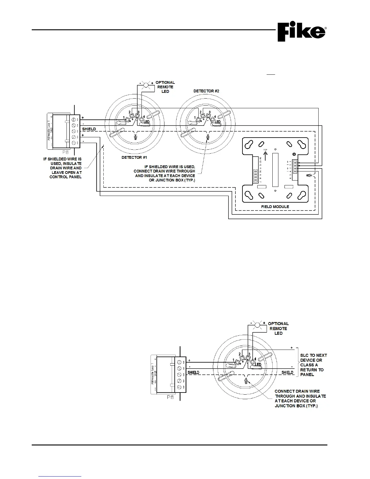
4.13.6.2 CLASS A OR CLASS X WIRING
Exhibit 4-19 shows typical wiring of a supervised and power-limited four-wire SLC that meets NFPA 72, Class
A or Class X requirements. This wiring method includes a redundant path. In the event of a single wire
break, the communication to devices after the break continues. This wiring method will not support t-tapping
4.13.6.3 CLASS X WIRING
Class X wiring is the same as Class A wiring except that it utilizes isolator devices to provide short-circuit
protection for the signaling line circuit (SLC). The circuitry built-into the isolator devices allow communication
to devices to continue past a single short-circuit. Short circuit protection can be provided for the entire
signaling line circuit or for selected sections of the signaling line circuit. Isolator devices can be installed to
electrically isolate a zone of detectors and/or modules from the remainder of the loop by installing an isolator
type device at the point where the SLC enters and leaves the zone. A maximum of 50 devices can be
installed between two isolator type devices.
Note: If using isolator bases, the loop + is separated between terminal 1 (in) and terminal 2 (out).
4.13.6.4 REMOTE LED WIRING
The detector base has the ability to
attach a remote LED as shown in
Exhibit 4-20. Power for operation of
the LED is drawn from the control
panel’s addressable loop. The
addressable loop is limited to a
maximum of 100 mA total for
addressable devices plus remote LED
devices.
Exhibit 4-19: Class A and Class X SLC Wiring
Exhibit 4-20: Remote LED Wiring