4.0 INSTALLATION
4-8 Cheetah Xi 50 Installation Manual UL S2203
Rev 6, 09/2015 P/N: 06-369 FM
4.9.4 INSTALL THE CHEETAH XI 50 CONTROLLER
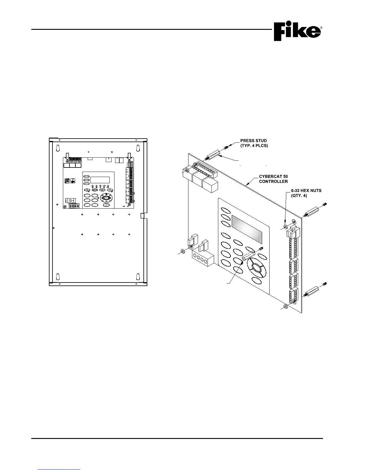
The following general steps shall be used to install the Cheetah Xi 50 controller:
1. Locate the four threaded press studs provided in the enclosure back-box for mounting the controller
board (See Exhibit 4-8) and install the four hex stand-offs (2.5”, M/F #6-32) supplied with the
enclosure onto the threaded press studs.
2. Locate the threaded press studs provided in the enclosure back-box for keypad support (See Exhibit
4-9) and install the hex stand-off (2.5”, F/F #6-32) supplied with the enclosure onto the threaded
press stud.
3. Align the mounting holes provided in the four corners of the controller board with the stand-offs and
secure in place using the four #6-32 hex nuts supplied with the enclosure (See Exhibit 4-9).
K5 K6
K7
JTAG
P10
24V
P5
P4
AUX#1 F4 4A
P3
P2
10-2620 REV
02-11544 REV A
F1
F2
F3 F6
F5
F4
CYBER CAT 50
FIKE CORPORATION
01:39:37A 06/14/2011
AL:000 SU:000 TR:000
BACK-BOX
CONTROLLER
Exhibit 4-8: Controller Mounting Location
2" F/F STANDOFF
(KEYPAD SUPPORT)
Exhibit 4-9: Controller Mounting
2.5” M/F STANDOFF
(TYP. 4 PLCS)
2.5” F/F STANDOFF
(KEYPAD SUPPORT)