3.0 SYSTEM COMPONENTS
UL S2203 Cheetah Xi 50 Installation Manual 3-5
FM P/N: 06-369 Rev 6, 09/2015
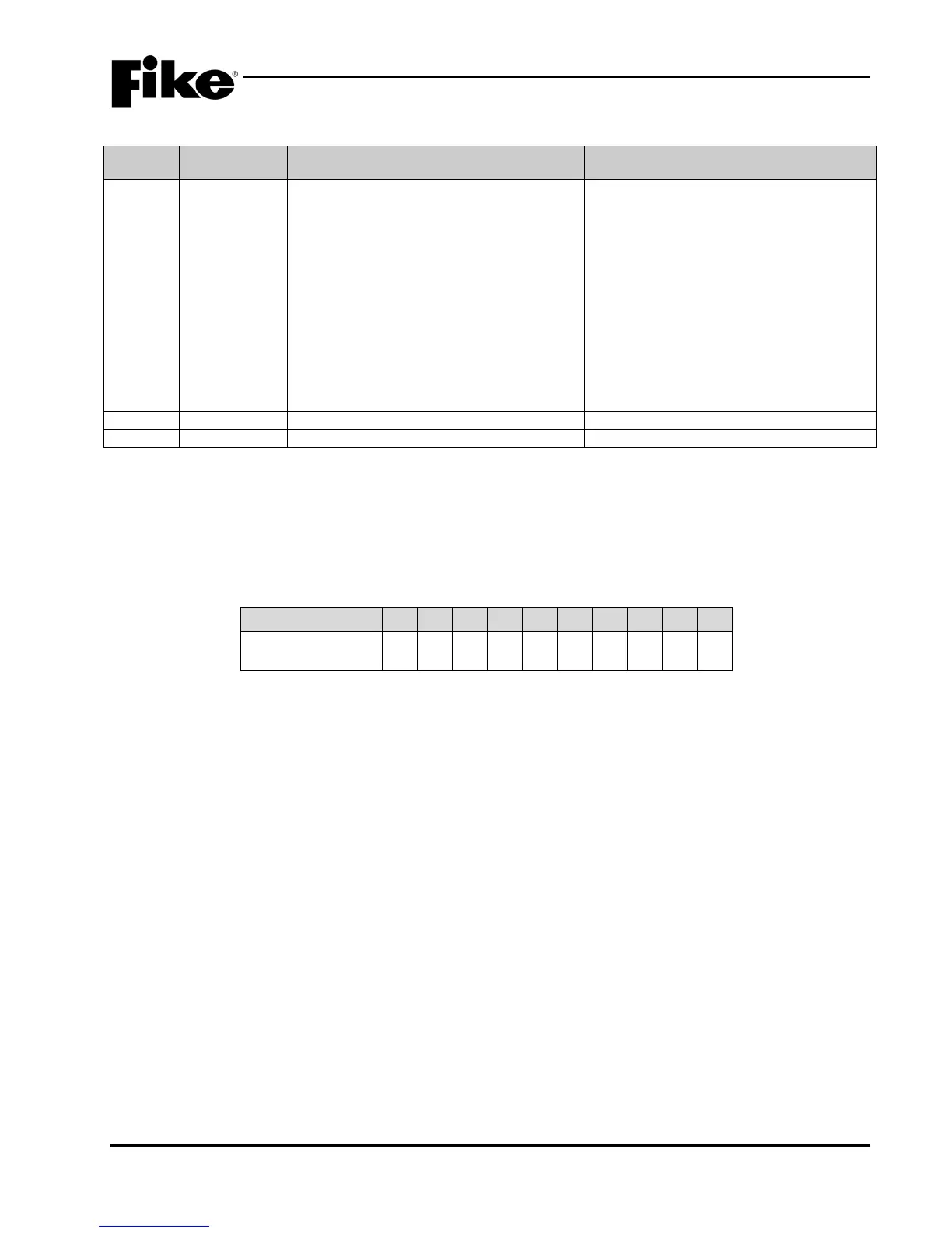
Exhibit 3-7: Cheetah Xi 50 Controller Terminal Specifications – Cont.
Function and Electrical
Ratings/Requirements
(--, ++, shld, -,
+)
• Power-limited and supervised
• Continuous, regulated 24 VDC @ 1.75A
maximum, regulated 28 volts maximum
• Supports Class B using 1.2KΩ EOL
resistor, P/N 10-2570 or Class A using
redundant wiring
• Can be programmed for Gentex or
System Sensor synchronization
protocols.
• Once sync is selected, programmable for
selective silence (strobes remain ON) or
silence both horn and strobe
T-tapping of circuit is NOT allowed
If using the synchronization protocol option,
both circuits must use the same protocol
(i.e. Gentex or System Sensor)
The circuits are either ON or OFF and can
not be configured for modulation patterns.
Refer to Fike document 06-186,
“Compatible Notification Appliances and
Releasing Devices Manual” for a list of
compatible NAC devices
Terminal blocks accept 12 – 24 AWG
3.2.1 NAC CIRCUIT LIMITATIONS
The NAC circuit field wiring resistance is limited by the amount of anticipated load. Many local authorities
require a voltage drop calculation be performed to demonstrate the lowest voltage present at the last device.
The designer shall determine the resistance of the wire specified and distance for the installation needs.
From this information, they can determine the total resistance for the circuit. Exhibit 3-8 provides the
maximum field wiring resistance for total device current that can also be used as a tool.
3.2.2 CONTROLLER TEST POINTS/VOLTAGES
The Cheetah Xi 50 controller has two primary test points. While viewing the panel display, TP1 is located in
the lower right corner of the board to the right of the board part number. TP2 is located just to the right of the
relay block in the upper left corner of the board and is labeled 24V.
TP1 = COM
This test point should be used when making DC voltage measurements on the control board. Connect the
voltmeter ground lead to this point, and then touch the positive lead to the point under test. This is the ground
reference for all points on the control board.
TP2 = 24V
This test point is the + side for the main controller 24VDC power buss. If the system does not seem to
operate properly even with AC power applied, connect the voltmeter positive lead to this point , and then
touch the ground lead to test point TP1 to verify the board voltage.
Ground Fault, TP1 to Chassis
With a normal panel and no ground fault, this voltage is 2.17 VDC nominal for Level 1 ground fault, and 5
VDC nominal for Level 2 ground fault. If a ground fault is present, this voltage will sway in either direction.
Ground fault detection impedances are 60K ohm between power ground and chassis ground or 1M ohm
between main power and chassis ground.
Max Current (Amps) .1 .2 .3 .4 .5 .6 .8 1.0 1.5 2.0
Audible Max Ω’s 24 12 8 6 4.8 4.0 3.0 2.4 1.6 1.2
Exhibit 3-8: NAC Circuit Field Wiring Resistance