APPENDIX A
UL S2203 Cheetah Xi 50 Installation Manual A-3
FM P/N: 06-369 Rev 6, 09/2015
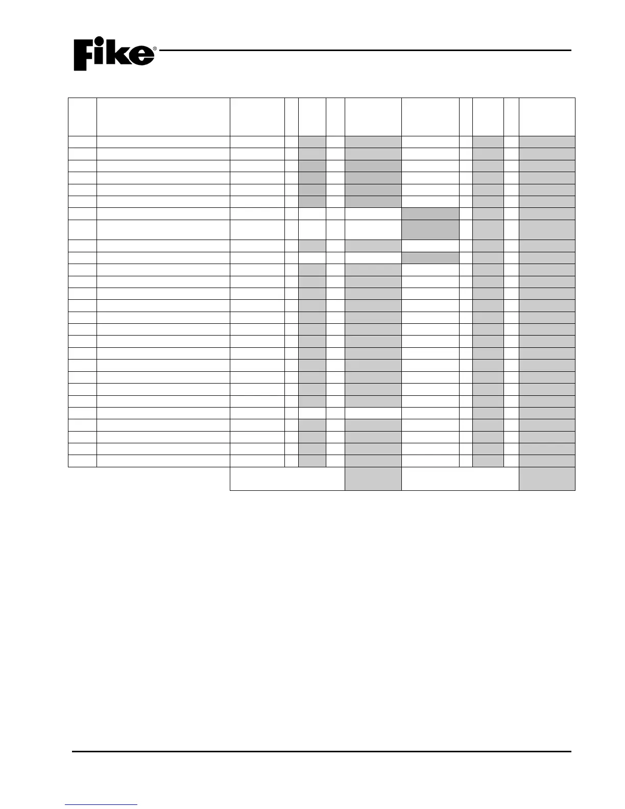
Section 3 – Auxiliary Power
Item Device Description
Standby
Current per
Unit (Amps)
Qty
Standby
Current per
Alarm
Current per
Unit (Amps)
Qty
Total Alarm
Current per
Unit (Amps)
3 55-052/053 RCM w/ Agent 0.0194 x = 0.010 x =
[Note 2]
55-052/053 RCM w/ Solenoid
Releasing Solenoid Coil [Note 3]
5
55-042/047 SCM w/ Solenoid
[Note 3]
NA x NA = NA x =
10-2413 Master-box Supervisor
6a Master-box Trip Coil [Note 3] NA x NA = NA x =
9 10-2630 2-button RDU 0.036 x = 0.139 x =
10-2411 LED Graphic Micro
10-2667 20-Zone Remote Annun.
16 10-2785 Relay Card [Note 5] 0.032 x = 0.256 x =
10-2777 Relay Assy. [Note 4]
[Note 5]
19 10-2770 HPM4 Relay [Note 5] NA x NA = NA 0.086 x =
10-2792 Class A Peripheral
10-2814 LOC Digital Paging
Total Aux. Power Standby
Current (Amps):
Total Aux. Power Alarm
Current (Amps):
Insert totals in Section 1 – Line Item 3.
Notes:
1. Indicate the current draw of the devices in this section only if the 24vdc power for device operation is supplied by the Cheetah Xi 50 system
controller. Typical for all devices.
2. Indicate quantity of ARMs or IRMs connected to the RCM.
3. Indicate alarm current draw of the coil that is connected to the module.
4. Assembly includes control card and relay bus card. Add the quantity of CRM4 and HPM4 relay cards installed on the bus card in rows 18 and
19.
5. Current values shown assume all relays are active.