CONTENT
UL S2203 Cheetah Xi 50 Installation Manual v
FM P/N: 06-369 Rev 6, 09/2015
LIST OF EXHIBITS
EXHIBIT DESCRIPTION PAGE
1-1 Related Documentation ................................................................................................... 1-3
2-1 Example Cheetah Xi 50 Block Diagram .......................................................................... 2-1
2-2 Minimum System Configurations ..................................................................................... 2-4
2-3 Minimum System Configurations – Cont. ........................................................................ 2-5
3-1 Cheetah Xi 50 System Package ...................................................................................... 3-1
3-2 System Ordering Formats ............................................................................................... 3-1
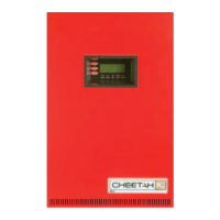
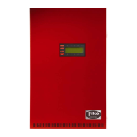
3-3 Cheetah Xi 50 Controller ................................................................................................. 3-1
3-4 Cheetah Xi 50 Terminal Block Locations ........................................................................ 3-2
3-5 Cheetah Xi 50 Controller Terminal Specifications ........................................................... 3-3
3-6 Cheetah Xi 50 Controller Terminal Specifications – Cont. .............................................. 3-4
3-7 Cheetah Xi 50 Controller Terminal Specifications – Cont. .............................................. 3-5
3-8 NAC Circuit Field Wiring Resistance ............................................................................... 3-5
3-9 Enclosure Ordering Formats ........................................................................................... 3-6
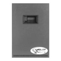
3-10 Cheetah Xi 50 Enclosure ................................................................................................. 3-7
3-11 Cheetah Xi 50 Enclosure with Dead-Front ...................................................................... 3-7
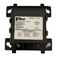
3-12 DACT ............................................................................................................................... 3-8
3-13 DACT Programmer .......................................................................................................... 3-8
3-14 Fourteen Button Remote Display Unit ............................................................................. 3-9
3-15 Ten Button Remote Display Unit ..................................................................................... 3-9
3-16 Two Button Remote Display Unit .................................................................................. 3-10
3-17 Ethernet Module ............................................................................................................ 3-10
3-18 Multi-Interface Module ................................................................................................... 3-10
3-19 LED Graphic Annunciator (Intelligent) ........................................................................... 3-11
3-20 Twenty Zone Remote Annunciator ................................................................................ 3-11
3-21 Relay Control Assembly ................................................................................................ 3-11
3-22 Relay Card ..................................................................................................................... 3-12
3-23 Class A Peripheral Bus Card ......................................................................................... 3-12
3-24 Photo Detector ............................................................................................................... 3-13
3-25 Ion Detector ................................................................................................................... 3-13
3-26 Photo/Heat Detector ...................................................................................................... 3-14
3-27 Heat Detector ................................................................................................................ 3-14
3-28 Photo Duct Detector ...................................................................................................... 3-15
3-29 Duct Detector Housing .................................................................................................. 3-15
3-30 FAAST Detector ............................................................................................................ 3-16
3-31 4-Inch Base ................................................................................................................... 3-17
3-32 6-Inch Base ................................................................................................................... 3-17
3-33 Sounder Base ................................................................................................................ 3-17
3-34 Relay Base .................................................................................................................... 3-17
3-35 Remote Annunciator ...................................................................................................... 3-18
3-36 Remote Test Station ...................................................................................................... 3-18
3-37 Remote Test Station with Key ....................................................................................... 3-18
3-38 Mini Monitor Module ...................................................................................................... 3-19
3-39 Monitor Module .............................................................................................................. 3-19
3-40 Pull Station .................................................................................................................... 3-20
3-41 Supervised Control Module ........................................................................................... 3-21
3-42 Solenoid Protection Assembly ....................................................................................... 3-21