46
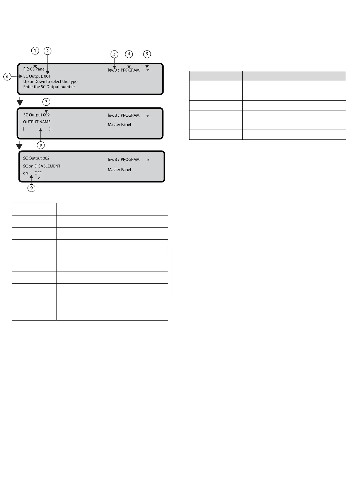
Figure 29: Selecting and programming SC active on
disablement options
If blinking, control panel working
properly
OUTPUT NAME
Enter or modify the relevant output name using the
alphanumeric keypad. The maximum number of
characters is twenty.
TRIGGER ZONE 1
Select the first zone for which events, defined later, the
output will become active. The entry 0000 means No Zone.
Numeric entry modes range from 0 to 128 for FC503 and 0
to 256 for FC506.
TRIGGER ZONE 2
Select the second zone for which events, defined later, the
output will become active. The entry 0000 means No Zone.
Numeric entry modes range from 0 to 128 for FC503 and 0
to 256 for FC506.
TRIGGER EVENT
Define, for both trigger zones, the event types valid to
activate the relevant output. The event type codes are
shown in Table 46.
Table 46: Trigger Event Codes
You can select more than one trigger event using the
multiple selection mode. The selected events are valid
for all trigger zones.
When zones trigger condition act in OR mode, it is
sufficient that the trigger condition of a single zone is
matched to activate the output.
SILENCEABLE
Use SILENCEABLE to select if the output stays active until
the SILENCE/RESOUND SOUNDERS key is pressed (on
option set) or stays active until the RESET key is pressed
(off option set).
Once a SILENCEABLE output has been silenced, it may be
reactivated by pressing the SILENCE/RESOUND
SOUNDERS key again.
MONOSTABLE
Set MONOSTABLE to ON to automatically deactivate the
relevant output when the MONOST. OUTPUT TIME
elapses.
The MONOST. OUTPUT TIME is set in the SYSTEM
section of the PROGRAM menu and its value is valid for
all outputs.
5 Key- network
The network option of the programming menu activates the
procedure to configure the FC500MFI modules.
Complete the following steps when all the control panels
and the FC500MFI modules are connected in the network:
1. Use the 5 Key to select network from the
Programming screen in the user interface. See
Figure 24, 0.
2. Use the left and right arrow keys or the ^ symbol
under the name of the selected module to select the
FC500MFI modules to be configured.
3. Enable a FC500MFI module with the Up arrow or
disable it with the Down arrow. The module name
will appear in uppercase if enabled.
4. Press the ENTER key to confirm.
In the ANALYZE status (lev.1 level), an acronym is used
to display the related status. The acronyms are:
OK! The net. device is sensed as connected and